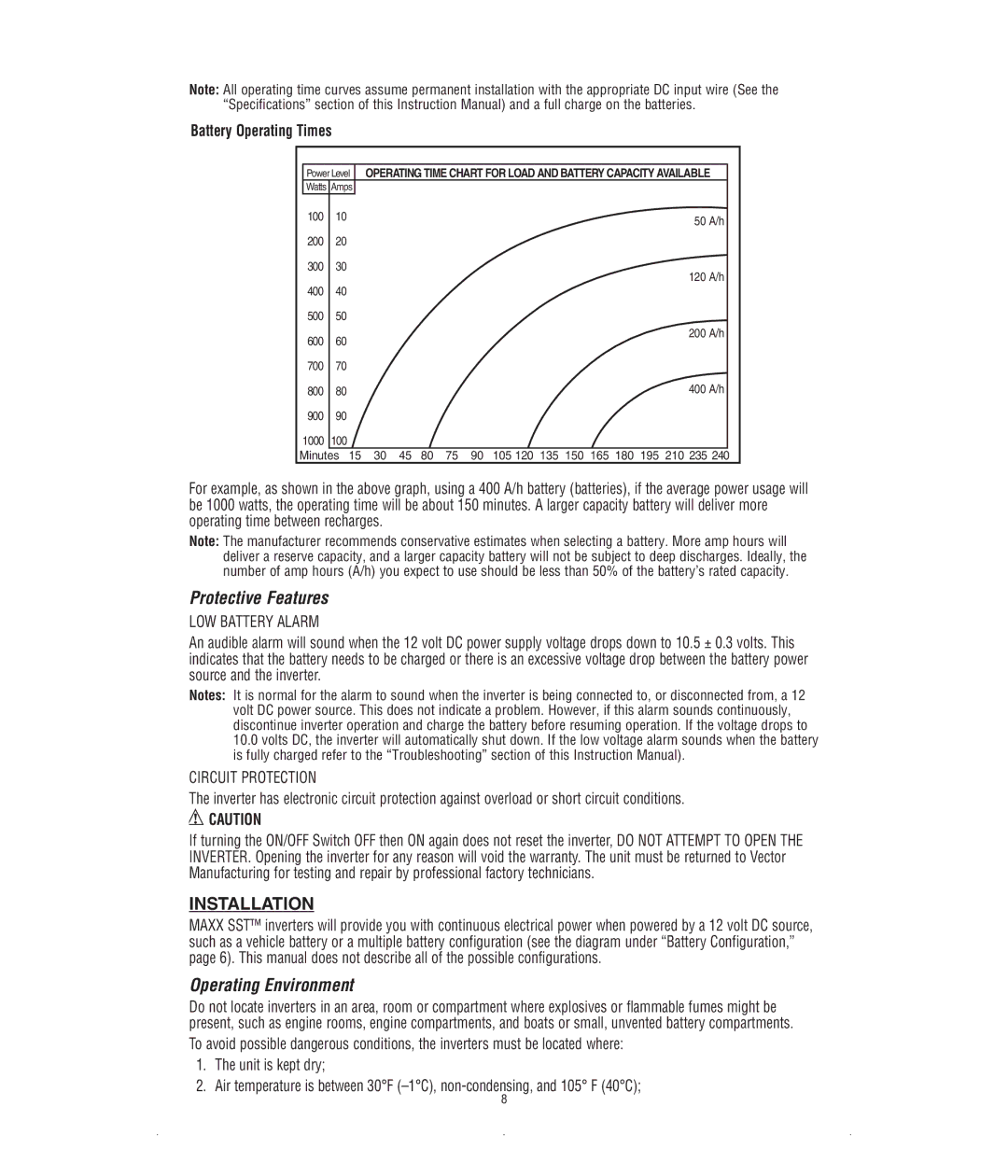
Note: All operating time curves assume permanent installation with the appropriate DC input wire (See the “Specifications” section of this Instruction Manual) and a full charge on the batteries.
Battery Operating Times
Power Level | OPERATING TIME CHART FOR LOAD AND BATTERY CAPACITY AVAILABLE | |
Watts Amps |
| |
100 | 10 | 50 A/h |
|
| |
200 | 20 |
|
300 | 30 | 120 A/h |
|
| |
40040
50050
600 | 60 |
|
|
|
|
|
| 200 A/h | |
|
|
|
|
|
|
|
| ||
700 | 70 |
|
|
|
|
|
|
|
|
800 | 80 |
|
|
|
|
|
| 400 A/h | |
900 | 90 |
|
|
|
|
|
|
|
|
1000 | 100 |
|
|
|
|
|
|
|
|
Minutes | 15 | 30 | 45 | 80 | 75 | 90 | 105 120 135 150 165 180 195 210 235 240 |
| |
For example, as shown in the above graph, using a 400 A/h battery (batteries), if the average power usage will be 1000 watts, the operating time will be about 150 minutes. A larger capacity battery will deliver more operating time between recharges.
Note: The manufacturer recommends conservative estimates when selecting a battery. More amp hours will deliver a reserve capacity, and a larger capacity battery will not be subject to deep discharges. Ideally, the number of amp hours (A/h) you expect to use should be less than 50% of the battery’s rated capacity.
Protective Features
LOW BATTERY ALARM
An audible alarm will sound when the 12 volt DC power supply voltage drops down to 10.5 ± 0.3 volts. This indicates that the battery needs to be charged or there is an excessive voltage drop between the battery power source and the inverter.
Notes: It is normal for the alarm to sound when the inverter is being connected to, or disconnected from, a 12 volt DC power source. This does not indicate a problem. However, if this alarm sounds continuously, discontinue inverter operation and charge the battery before resuming operation. If the voltage drops to
10.0volts DC, the inverter will automatically shut down. If the low voltage alarm sounds when the battery is fully charged refer to the “Troubleshooting” section of this Instruction Manual).
CIRCUIT PROTECTION
The inverter has electronic circuit protection against overload or short circuit conditions.
![]() CAUTION
CAUTION
If turning the ON/OFF Switch OFF then ON again does not reset the inverter, DO NOT ATTEMPT TO OPEN THE INVERTER. Opening the inverter for any reason will void the warranty. The unit must be returned to Vector Manufacturing for testing and repair by professional factory technicians.
INSTALLATION
MAXX SST™ inverters will provide you with continuous electrical power when powered by a 12 volt DC source, such as a vehicle battery or a multiple battery configuration (see the diagram under “Battery Configuration,” page 6). This manual does not describe all of the possible configurations.
Operating Environment
Do not locate inverters in an area, room or compartment where explosives or flammable fumes might be present, such as engine rooms, engine compartments, and boats or small, unvented battery compartments.
To avoid possible dangerous conditions, the inverters must be located where:
1.The unit is kept dry;
2.Air temperature is between 30°F
8