T1 FIBER OPTIC LINE EXTENDER/SIMULATOR
Table
Number | Setting | Description | |
|
|
| |
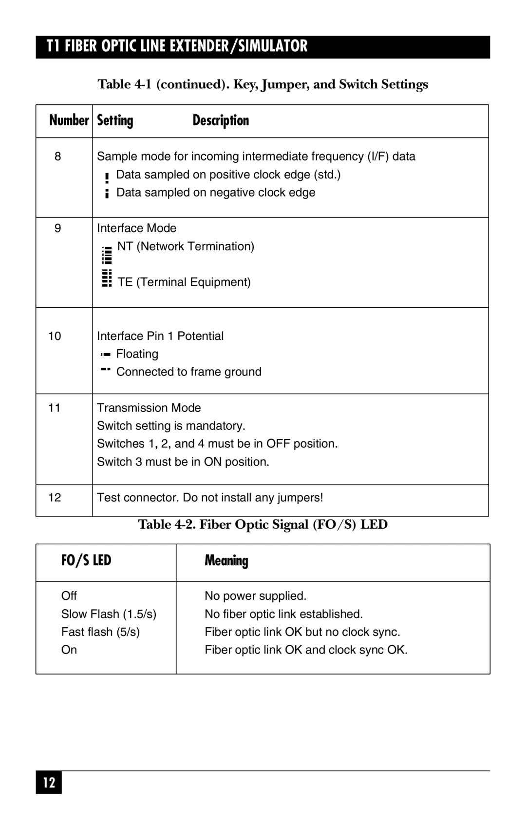
8 | Sample mode for incoming intermediate frequency (I/F) data | ||
| Data sampled on positive clock edge (std.) | ||
| Data sampled on negative clock edge | ||
|
|
|
|
9 | Interface Mode |
| |
| NT (Network Termination) | ||
| TE (Terminal Equipment) | ||
|
|
| |
10 | Interface Pin 1 Potential | ||
| Floating |
| |
| Connected to frame ground | ||
|
|
| |
11 | Transmission Mode | ||
| Switch setting is mandatory. | ||
| Switches 1, 2, and 4 must be in OFF position. | ||
| Switch 3 must be in ON position. | ||
|
|
| |
12 | Test connector. Do not install any jumpers! | ||
|
|
| |
| Table | ||
|
|
|
|
FO/S LED |
| Meaning | |
|
|
|
|
Off |
|
| No power supplied. |
Slow Flash (1.5/s) |
| No fiber optic link established. | |
Fast flash (5/s) |
| Fiber optic link OK but no clock sync. | |
On |
|
| Fiber optic link OK and clock sync OK. |
|
|
|
|
12
