APPENDIX: Fiber Optic Planning Guidelines
A.2 Fiber Optic Calculation
STEP 1: ATTENUATION CONSIDERATIONS
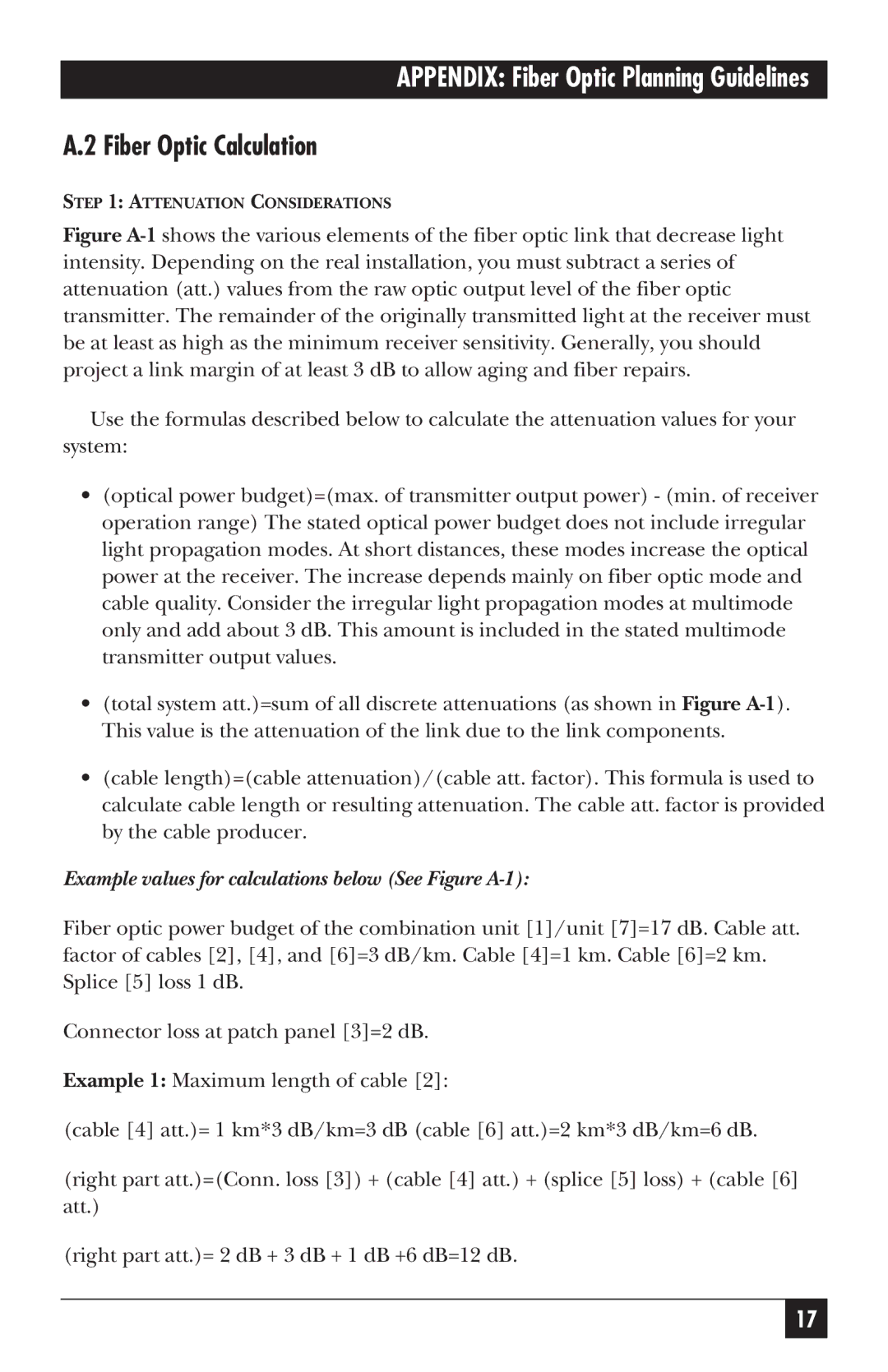
Figure A-1 shows the various elements of the fiber optic link that decrease light intensity. Depending on the real installation, you must subtract a series of attenuation (att.) values from the raw optic output level of the fiber optic transmitter. The remainder of the originally transmitted light at the receiver must be at least as high as the minimum receiver sensitivity. Generally, you should project a link margin of at least 3 dB to allow aging and fiber repairs.
Use the formulas described below to calculate the attenuation values for your system:
•(optical power budget)=(max. of transmitter output power) - (min. of receiver operation range) The stated optical power budget does not include irregular light propagation modes. At short distances, these modes increase the optical power at the receiver. The increase depends mainly on fiber optic mode and cable quality. Consider the irregular light propagation modes at multimode only and add about 3 dB. This amount is included in the stated multimode transmitter output values.
•(total system att.)=sum of all discrete attenuations (as shown in Figure A-1). This value is the attenuation of the link due to the link components.
•(cable length)=(cable attenuation)/(cable att. factor). This formula is used to calculate cable length or resulting attenuation. The cable att. factor is provided by the cable producer.
Example values for calculations below (See Figure A-1):
Fiber optic power budget of the combination unit [1]/unit [7]=17 dB. Cable att. factor of cables [2], [4], and [6]=3 dB/km. Cable [4]=1 km. Cable [6]=2 km. Splice [5] loss 1 dB.
Connector loss at patch panel [3]=2 dB.
Example 1: Maximum length of cable [2]:
(cable [4] att.)= 1 km*3 dB/km=3 dB (cable [6] att.)=2 km*3 dB/km=6 dB.
(right part att.)=(Conn. loss [3]) + (cable [4] att.) + (splice [5] loss) + (cable [6] att.)
(right part att.)= 2 dB + 3 dB + 1 dB +6 dB=12 dB.
17