Chapter 2: Overview
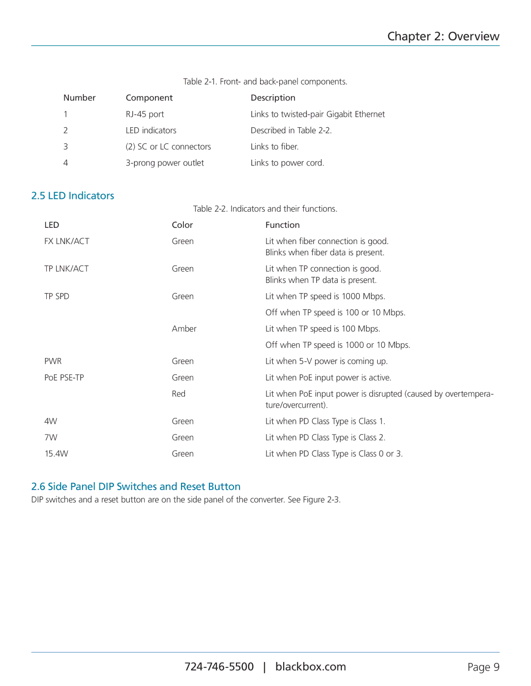
| Table | |
Number | Component | Description |
1 | Links to | |
2 | LED indicators | Described in Table |
3 | (2) SC or LC connectors | Links to fiber. |
4 | Links to power cord. | |
2.5 LED Indicators |
|
|
| Table | |
LED | Color | Function |
FX LNK/ACT | Green | Lit when fiber connection is good. |
|
| Blinks when fiber data is present. |
TP LNK/ACT | Green | Lit when TP connection is good. |
|
| Blinks when TP data is present. |
TP SPD | Green | Lit when TP speed is 1000 Mbps. |
|
| Off when TP speed is 100 or 10 Mbps. |
| Amber | Lit when TP speed is 100 Mbps. |
|
| Off when TP speed is 1000 or 10 Mbps. |
PWR | Green | Lit when |
PoE | Green | Lit when PoE input power is active. |
| Red | Lit when PoE input power is disrupted (caused by overtempera- |
|
| ture/overcurrent). |
4W | Green | Lit when PD Class Type is Class 1. |
7W | Green | Lit when PD Class Type is Class 2. |
15.4W | Green | Lit when PD Class Type is Class 0 or 3. |
2.6 Side Panel DIP Switches and Reset Button
DIP switches and a reset button are on the side panel of the converter. See Figure
| Page 9 |
