SHM-B ASYNC

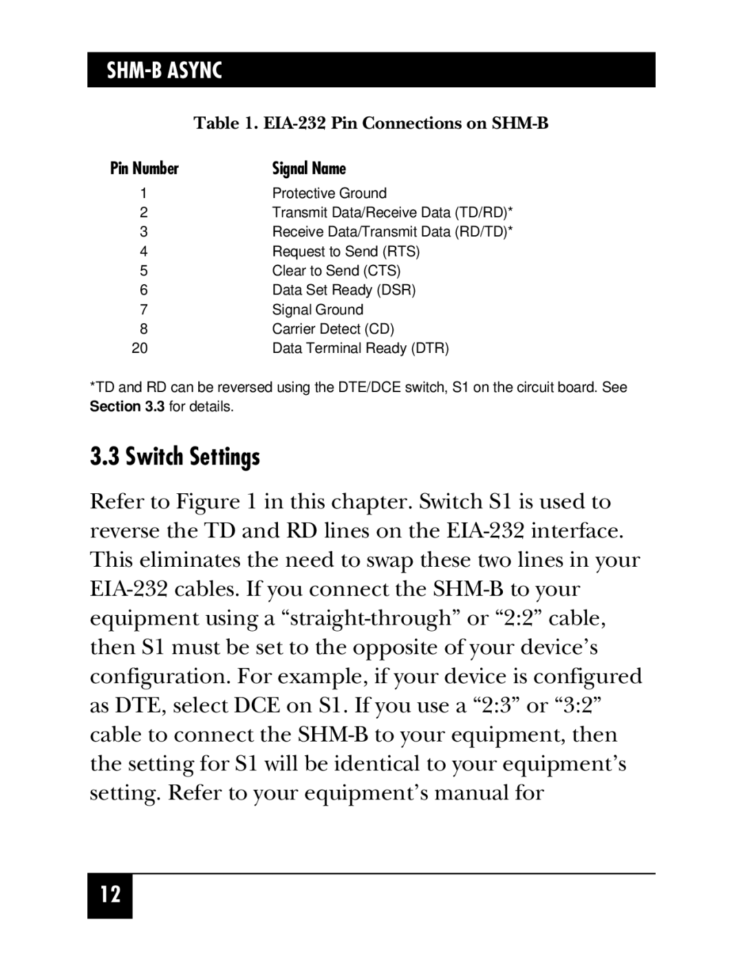
Table 1. EIA-232 Pin Connections on SHM-B

Pin Number

Signal Name

1Protective Ground

2Transmit Data/Receive Data (TD/RD)*

3Receive Data/Transmit Data (RD/TD)*

4Request to Send (RTS)

5Clear to Send (CTS)

6Data Set Ready (DSR)

7Signal Ground

8Carrier Detect (CD)

20

Data Terminal Ready (DTR)

*TD and RD can be reversed using the DTE/DCE switch, S1 on the circuit board. See Section 3.3 for details.

3.3 Switch Settings

Refer to Figure 1 in this chapter. Switch S1 is used to reverse the TD and RD lines on the EIA-232 interface. This eliminates the need to swap these two lines in your EIA-232 cables. If you connect the SHM-B to your equipment using a “straight-through” or “2:2” cable, then S1 must be set to the opposite of your device’s configuration. For example, if your device is configured as DTE, select DCE on S1. If you use a “2:3” or “3:2” cable to connect the SHM-B to your equipment, then the setting for S1 will be identical to your equipment’s setting. Refer to your equipment’s manual for

12

Page 13
Image 13
Black Box ME810, Short-Haul Modem B, ME800A-R2, ME805-C-R2 manual Switch Settings, EIA-232 Pin Connections on SHM-B