Front Quick Release Anatomy
Fig. 9
Brake lever in the set position
with button depressed.
Cam Housing
Conical
Springs
Fig. 14
ParkingBrakeButton
Adjusting Nut
Quick Release Lever
Rod
Fig. 13
ParkingBrakeButton
Brake Lever
Body
Brake lever
Lock Ring Barrel Adjuster
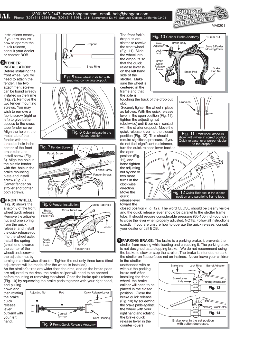
7 PARKING BRAKE: The brake is a parking brake, it prevents the stroller from moving while loading and unloading it. The parking brake is not designed as a stopping brake. We do not recommend using the brake to slow or stop the stroller. The brake is intended to park the stroller on flat surfaces not on inclines. Never leave your children in the stroller
unattended with or without the parking
brake set! After installing the front
wheel, the brake caliper will need to be
placed in the closed
position. Close the brake quick release
(Fig. 10) by squeezing the brake pads against the wheel with your
right hand and rotating
the brake quick release lever in the
counter (over)
Fig. 12 Quick Release in the closed position and parallel to frame tube.
Fabric
Screw
Hole
Brake
Mounting
Plate Hole
Cross Tube Hole
Fig. 8 Fender Installation
Fabric Screw
Fender Hole
Fender Screw
Metal Tab Hole
Fabric Screw Fender Screws
Fig. 11 Front wheel dropouts
shown with wheel in correct position. Quick release lever perpendicular to the dropout.
Dropouts
Brake Pad
Brake
Pad Nut
Brake
Quick
Release
Lever
Lock
Nut
Brake & Fender
Mounting Screw
Barrel
Adjuster
Brake Body
10 mm Nut
Caliper Brake Anatomy
Fig. 10
The front fork’s dropouts are slotted to receive
the front wheel (Fig. 11). Slide the wheel into the dropouts so
that the quick
release lever is on the left hand side of the
stroller. Make sure the wheel is centered in the
frame and that the axle is
touching the back of the drop out slot.
Securely tighten the wheel in place as follows: With the quick release
lever in the open position (Fig. 11), tighten the adjusting nut
(clockwise) until it comes in contact with the stroller dropout. Move the quick release lever to the closed position (Fig. 12). This should require significant pressure. If you do not feel significant resistance, turn the quick release lever back to the open
position (Fig. 11), and hand tighten the adjusting nut by one or two more turns in the clockwise direction. Move the quick release lever toward the
closed position (Fig. 12). The word CLOSE should be clearly visible and the quick release lever should be parallel to the stroller frame tube. It should require considerable pressure (80-105inch-pounds) to close the lever when properly adjusted. NOTE: Follow all instructions exactly. If you are unsure how to operate the quick release, consult your dealer or call BOB.
MA0201

UAL

(800) 893-2447 www.bobgear.com email- bob@bobgear.com

Phone: (805) 541-2554 Fax: (805) 543-8464,3641 Sacramento Dr. #3 San Luis Obispo, California 93401


instructions exactly. If you are unsure how to operate the quick release, consult your dealer or contact BOB.

5FENDER INSTALLATION: Before installing the front wheel, you will need to attach the fender. The two attachment screws can be found already installed on the frame (Fig. 7). Remove the two fender mounting screws. You may wish to remove a fabric screw (right or left) to give better access to the cross tube fender screw. Align the hole in the metal tab of the fender with the threaded hole in the center of the front cross tube and install screw (Fig.

8). Align the hole in the plastic fender with the hole in the brake mounting plate and install screw (Fig. 8). Center fender on stroller and tighten both screws.

Dropout

Snap Ring

Fig. 5 Rear wheel installed with

snap ring contacting dropout.

Fig. 6 Quick release in the

closed position.

Fig. 7 Fender Screws

6FRONT WHEEL:

(Fig. 9) shows the anatomy of the front wheel quick release.

Remove the adjuster

nut and one spring from the quick

release, and install

the quick release rod into the wheel axle.

Install the spring (small end towards

the center of the wheel) and screw on the adjuster nut by

turning in a clockwise direction. Tighten the nut only three turns (final adjustment will be made after the wheel is installed).

As the stroller’s tires are wider than the rims, and as the brake pads are adjusted to the rims, the brake caliper will need to be opened before mounting or removing the wheel. Open the brake quick release (Fig. 10) by squeezing the brake pads together with your right hand, and pulling

down and then rotating

the brake quick

release

lever outward with your left

hand.

Page 2
Image 2
BOB MA0201 operating instructions Ual, Front Wheel

MA0201 specifications

BOB MA0201 is a cutting-edge module designed to cater to the needs of IoT (Internet of Things) applications through its robust features and versatile technologies. At the heart of BOB MA0201 is the ability to seamlessly connect various devices, enabling efficient communication and data exchange within a network.

One of the main features of the BOB MA0201 is its built-in microcontroller which supports multiple communication protocols, including Wi-Fi, Bluetooth, and Zigbee. This versatility allows developers to choose the best communication method for their specific use case, whether that is for indoor or outdoor applications. Furthermore, the module is designed to operate in both a peer-to-peer network and a centralized hub setup, making it adaptable to different system architectures.

The BOB MA0201 comes equipped with a comprehensive set of sensors, including temperature, humidity, and motion sensors, making it an ideal choice for environmental monitoring and smart home applications. The integration of these sensors allows users to gather real-time data, which can be analyzed to make informed decisions concerning resource management and energy efficiency.

In terms of technology, the BOB MA0201 leverages low-power consumption, enabling long-lasting battery life for portable applications. The module is also compatible with various development platforms, making it accessible to both beginner and experienced developers. With support for popular programming languages, users can easily customize the functionality of the BOB MA0201 to meet their specific project requirements.

Moreover, the module is designed with security in mind, employing encryption protocols to safeguard data transmission. This feature is particularly crucial for IoT applications where data integrity is paramount.

In summary, the BOB MA0201 stands out due to its flexibility in communications, integrated sensor functionalities, low power consumption, and robust security measures. This combination makes it an attractive option for developers looking to build innovative IoT solutions. With its user-friendly design and extensive compatibility, the BOB MA0201 empowers users to harness the potential of connected devices for enhanced automation and control in various applications.