Adjusting the quick release mechanism |
|
|
| Fig. 7 Fender Screws |
| |
|
|
|
|
| ||
The wheel hub is clamped in place by the force of the quick release cam pushing against | Fabric Screw |
| ||||
one dropout and pulling the tension adjusting nut, by way of the skewer, against the |
|
| ||||
|
|
|
| |||
other dropout. The amount of clamping force is controlled by the tension adjusting nut. |
|
|
| |||
Turning the tension adjusting nut clockwise while keeping the cam lever from rotating |
|
|
| |||
increases clamping force; turning it counterclockwise while keeping the cam lever from |
|
|
| |||
rotating reduces clamping force. Less than half a turn of the tension adjusting nut can |
|
| Fabric Screw | |||
make the difference between safe clamping force and unsafe clamping force. |
|
|
| |||
|
|
| Fender Screws | |||
Front Wheel Secondary Retention Devices |
|
|
|
|
| |
|
|
|
|
|
| |
All 2007 and newer BOB Strollers have front forks which utilize secondary wheel retention |
|
|
| |||
devices designed to help keep the wheel from disengaging if the quick release is |
|
|
|
| ||
incorrectly adjusted. Secondary retention devices are not a substitute for correct quick |
|
|
| |||
release adjustment. The secondary retention devices on your stroller are the integral |
|
|
| |||
type that is formed into the outer faces of the front fork dropouts. |
|
|
|
|
| |
WARNING: Do not remove or disable secondary retention devices. As its name | Fig. 8 Fender Installation | Metal Tab Hole | ||||
implies, they serve as a |
|
|
| |||
not adjusted correctly, the secondary retention devices can reduce the risk of the | Brake | Cross Tube Hole |
| |||
wheel disengaging from the fork. Removing or disabling the secondary retention | Mounting |
|
| |||
devices may also void the warranty. |
|
|
| Plate Hole |
|
|
Secondary retention devices are not a substitute for correct quick release |
|
|
|
| ||
adjustment. Failure to properly adjust the quick release mechanism can cause |
|
|
|
| ||
the wheel to wobble or disengage, which could cause you to lose control and fall, |
|
| Fender | |||
resulting in serious injury or death. |
|
|
|
|
| Screw |
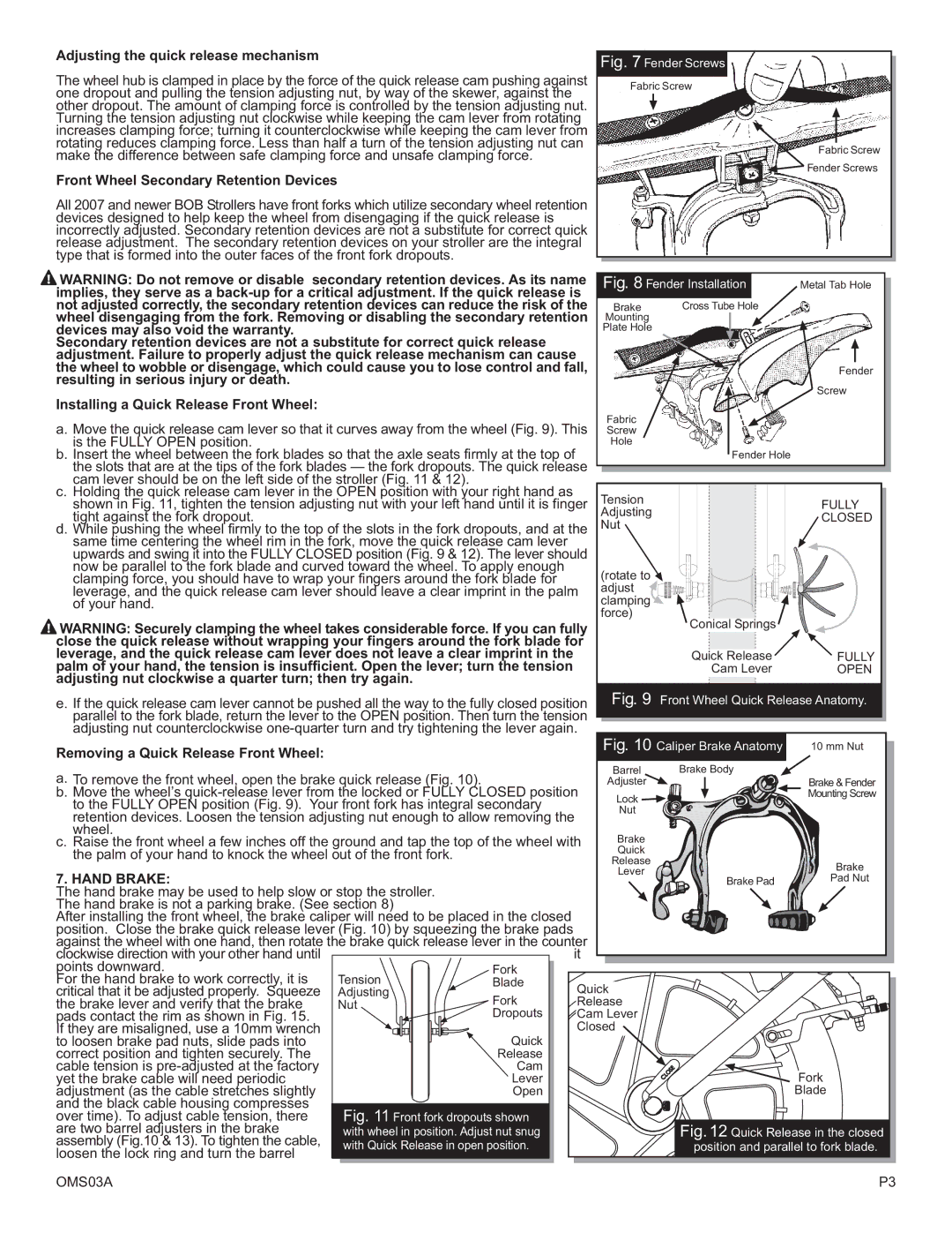
Installing a Quick Release Front Wheel: |
|
|
|
|
| |
|
|
|
|
|
| |
a. Move the quick release cam lever so that it curves away from the wheel (Fig. 9). This | Fabric |
|
| |||
Screw |
|
| ||||
is the FULLY OPEN position. |
|
|
| Hole |
|
|
b. Insert the wheel between the fork blades so that the axle seats firmly at the top of |
|
| Fender Hole |
| ||
the slots that are at the tips of the fork blades — the fork dropouts. The quick release |
|
|
| |||
cam lever should be on the left side of the stroller (Fig. 11 & 12). |
|
|
|
|
| |
c. Holding the quick release cam lever in the OPEN position with your right hand as |
| Tension |
|
| ||
shown in Fig. 11, tighten the tension adjusting nut with your left hand until it is finger |
| FULLY | ||||
tight against the fork dropout. |
|
|
| Adjusting |
| CLOSED |
d. While pushing the wheel firmly to the top of the slots in the fork dropouts, and at the | Nut |
|
| |||
same time centering the wheel rim in the fork, move the quick release cam lever |
|
|
|
| ||
upwards and swing it into the FULLY CLOSED position (Fig. 9 & 12). The lever should |
|
|
| |||
now be parallel to the fork blade and curved toward the wheel. To apply enough |
| (rotate to |
|
| ||
clamping force, you should have to wrap your fingers around the fork blade for |
|
|
| |||
leverage, and the quick release cam lever should leave a clear imprint in the palm | adjust |
|
| |||
of your hand. |
|
|
| clamping |
|
|
WARNING: Securely clamping the wheel takes considerable force. If you can fully | force) | Conical Springs |
| |||
|
| |||||
close the quick release without wrapping your fingers around the fork blade for |
|
|
| |||
leverage, and the quick release cam lever does not leave a clear imprint in the |
|
| Quick Release | FULLY | ||
palm of your hand, the tension is insufficient. Open the lever; turn the tension |
|
| Cam Lever | OPEN | ||
adjusting nut clockwise a quarter turn; then try again. |
|
|
|
|
| |
e. If the quick release cam lever cannot be pushed all the way to the fully closed position | Fig. 9 | Front Wheel Quick Release Anatomy. | ||||
parallel to the fork blade, return the lever to the OPEN position. Then turn the tension |
|
|
| |||
adjusting nut counterclockwise | Fig. 10 Caliper Brake Anatomy |
| ||||
Removing a Quick Release Front Wheel: |
|
|
| 10 mm Nut | ||
|
|
|
|
|
| |
a. To remove the front wheel, open the brake quick release (Fig. 10). |
|
| Barrel | Brake Body |
| |
|
| Adjuster |
| Brake & Fender | ||
b. Move the wheel’s | Lock |
| Mounting Screw | |||
to the FULLY OPEN position (Fig. 9). Your front fork has integral secondary |
|
|
| |||
| Nut |
|
| |||
retention devices. Loosen the tension adjusting nut enough to allow removing the |
|
|
| |||
|
|
|
| |||
wheel. |
|
|
| Brake |
|
|
c. Raise the front wheel a few inches off the ground and tap the top of the wheel with |
|
| ||||
the palm of your hand to knock the wheel out of the front fork. |
|
| Quick |
|
| |
|
|
|
| Release |
| Brake |
7. HAND BRAKE: |
|
|
| Lever |
| |
|
|
|
| Pad Nut | ||
|
|
|
|
| ||
The hand brake may be used to help slow or stop the stroller. |
|
|
|
|
| |
The hand brake is not a parking brake. (See section 8) |
|
|
|
|
| |
After installing the front wheel, the brake caliper will need to be placed in the closed |
|
|
|
| ||
position. Close the brake quick release lever (Fig. 10) by squeezing the brake pads |
|
|
|
| ||
against the wheel with one hand, then rotate the brake quick release lever in the counter |
|
|
| |||
clockwise direction with your other hand until |
| it |
|
|
| |
points downward. |
| Fork |
|
|
|
|
For the hand brake to work correctly, it is | Tension | Blade | Quick |
|
| |
critical that it be adjusted properly. Squeeze | Adjusting | Fork |
|
| ||
the brake lever and verify that the brake | Nut | Release |
|
| ||
pads contact the rim as shown in Fig. 15. |
| Dropouts | Cam Lever |
|
| |
If they are misaligned, use a 10mm wrench |
|
| Closed |
|
| |
to loosen brake pad nuts, slide pads into |
| Quick |
|
|
|
|
correct position and tighten securely. The |
| Release |
|
|
|
|
cable tension is |
| Cam |
|
|
|
|
yet the brake cable will need periodic |
| Lever |
|
|
| Fork |
adjustment (as the cable stretches slightly |
| Open |
|
|
| Blade |
and the black cable housing compresses | Fig. 11 Front fork dropouts shown |
|
|
|
| |
over time). To adjust cable tension, there |
|
| Fig. 12 Quick Release in the closed | |||
are two barrel adjusters in the brake | with wheel in position. Adjust nut snug |
|
| |||
assembly (Fig.10 & 13). To tighten the cable, | with Quick Release in open position. |
|
| position and parallel to fork blade. | ||
loosen the lock ring and turn the barrel |
|
| ||||
|
|
|
|
|
| |
OMS03A |
|
|
|
|
| P3 |