4.0 Installation
The FSP is designed to be mounted on a counter top or shelf. However, prior to site preparation and installation, the printer should be powered up and run in the self test mode. Lay the printer flat on a counter. Please confirm that the line voltage agrees with the voltage listed on the label affixed to the side of the unit (see figure 4). Attach the AC cord and serial/remote interface cables into the proper connectors as shown in figure 4. Turn power on (figure 2) and you will hear the cutter motor cycle. The LCD will display PAPER OUT.
4.1 Loading Flight Strips
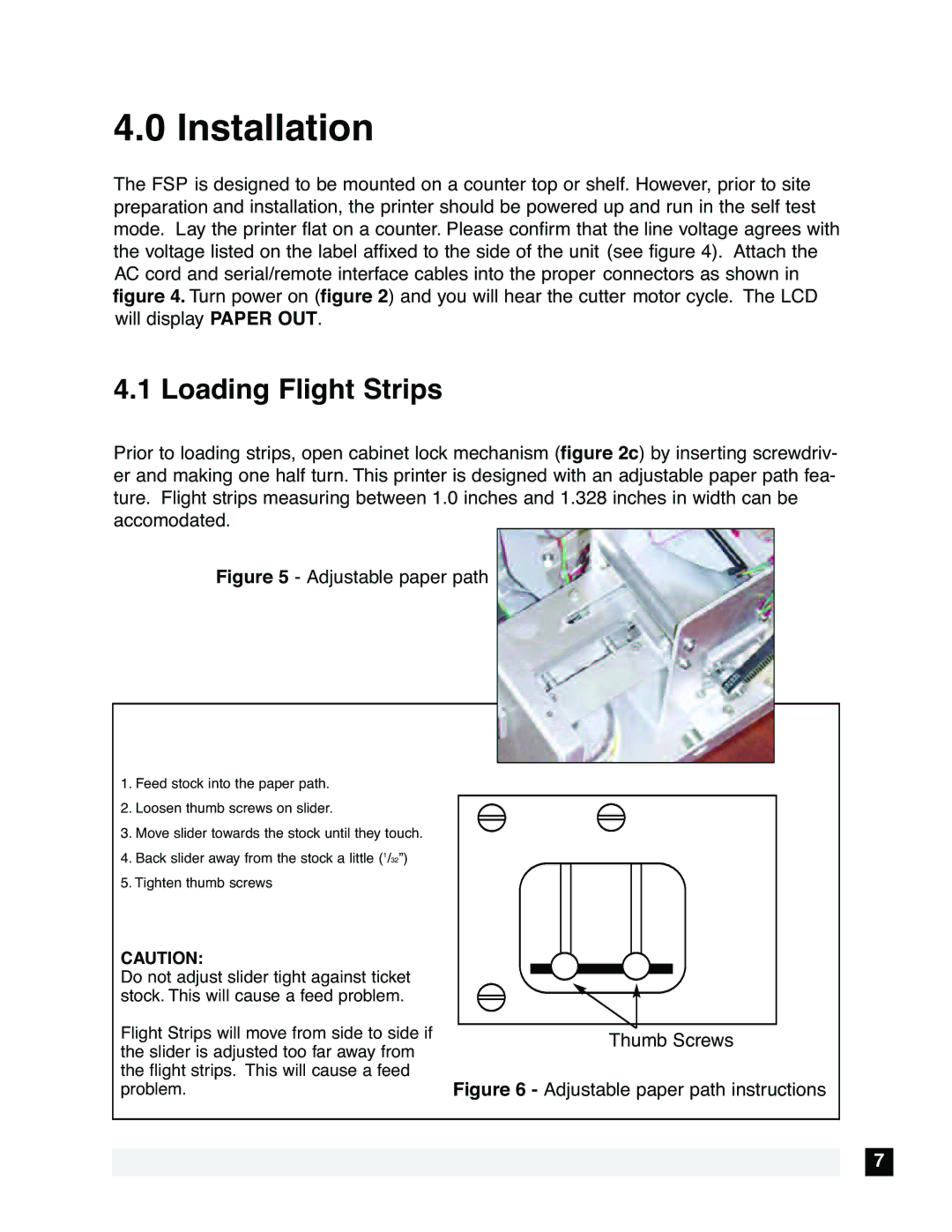
Prior to loading strips, open cabinet lock mechanism (figure 2c) by inserting screwdriv- er and making one half turn. This printer is designed with an adjustable paper path fea- ture. Flight strips measuring between 1.0 inches and 1.328 inches in width can be accomodated.
Figure 5 - Adjustable paper path
1.Feed stock into the paper path.
2.Loosen thumb screws on slider.
3.Move slider towards the stock until they touch.
4.Back slider away from the stock a little (1/32”)
5.Tighten thumb screws
CAUTION:
Do not adjust slider tight against ticket stock. This will cause a feed problem.
Flight Strips will move from side to side if the slider is adjusted too far away from the flight strips. This will cause a feed problem.
Thumb Screws
Figure 6 - Adjustable paper path instructions
7
