Section 2: Assembly 7

C

P

N


O

Figure 2-3 Attach handlebars.

6.Thread the height adjustment screw (F, Figure 2-2) into the hole in the handlebar cross-brace, making sure that the raised keys on the washer fit into the slot on the height adjustment bracket. Tighten the height adjustment screw securely. Next, securely tighten the two screws and nuts in the ends of the handlebar (M, Figure 2-2).

G

Figure 2-4: Carefully unwrap Wheel Gear Lever and move lever to DISENGAGE.

7.To remove the tiller from its shipping platform, first carefully unwrap the wheel gear cable (with attached lever - see Figure 2-4) from around the chassis. Move the Wheel Gear Lever (G) to the DISENGAGE position--this allows the wheels to rotate freely. Use the handlebars to roll the tiller off the platform.

NOTE: The Wheel Gear Lever will be installed later in this procedure.

IMPORTANT: Use the DISENGAGE posi- tion only when the engine is not running. Before starting the engine, the Wheel Gear Lever must be placed in the ENGAGE posi- tion (see Section 3 for details).

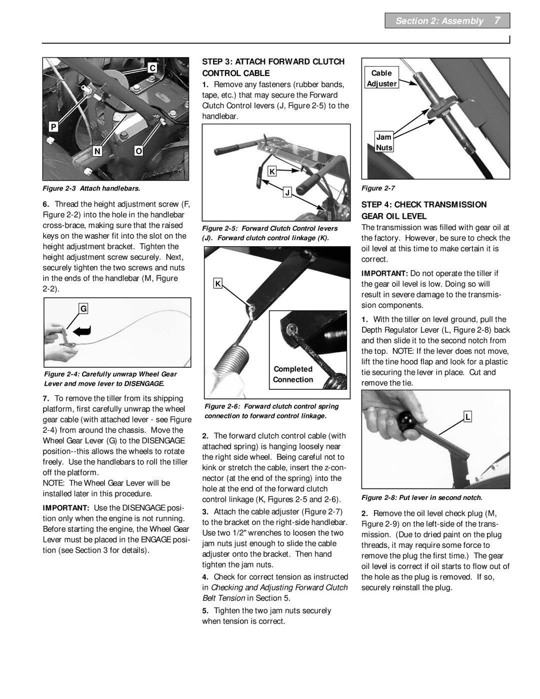
STEP 3: ATTACH FORWARD CLUTCH CONTROL CABLE

1.Remove any fasteners (rubber bands, tape, etc.) that may secure the Forward Clutch Control levers (J, Figure 2-5) to the handlebar.

K

J

Figure 2-5: Forward Clutch Control levers

(J). Forward clutch control linkage (K).

K

Completed

Connection

Figure 2-6: Forward clutch control spring connection to forward control linkage.

2.The forward clutch control cable (with attached spring) is hanging loosely near the right side wheel. Being careful not to kink or stretch the cable, insert the z-con- nector (at the end of the spring) into the hole at the end of the forward clutch control linkage (K, Figures 2-5 and 2-6).

3.Attach the cable adjuster (Figure 2-7) to the bracket on the right-side handlebar. Use two 1/2" wrenches to loosen the two jam nuts just enough to slide the cable adjuster onto the bracket. Then hand tighten the jam nuts.

4.Check for correct tension as instructed in Checking and Adjusting Forward Clutch Belt Tension in Section 5.

5.Tighten the two jam nuts securely when tension is correct.

Cable

Adjuster

Jam

Nuts

Figure 2-7

STEP 4: CHECK TRANSMISSION GEAR OIL LEVEL

The transmission was filled with gear oil at the factory. However, be sure to check the oil level at this time to make certain it is correct.

IMPORTANT: Do not operate the tiller if the gear oil level is low. Doing so will result in severe damage to the transmis- sion components.

1.With the tiller on level ground, pull the Depth Regulator Lever (L, Figure 2-8) back and then slide it to the second notch from the top. NOTE: If the lever does not move, lift the tine hood flap and look for a plastic tie securing the lever in place. Cut and remove the tie.

L

Figure 2-8: Put lever in second notch.

2.Remove the oil level check plug (M, Figure 2-9) on the left-side of the trans- mission. (Due to dried paint on the plug threads, it may require some force to remove the plug the first time.) The gear oil level is correct if oil starts to flow out of the hole as the plug is removed. If so, securely reinstall the plug.

Page 7
Image 7
Bolens 12226 owner manual Attach Forward Clutch Control Cable, Tighten the two jam nuts securely when tension is correct

12226 specifications

The Bolens 12226 is a powerful and versatile two-stage snowblower designed to tackle heavy snowfall and icy conditions with ease. It stands out in the market for its robust construction and innovative technologies, making it an essential tool for homeowners living in regions prone to harsh winter weather.

At the heart of the Bolens 12226 is its reliable 208cc PowerMore engine, engineered for maximum performance and durability. The engine's 4-cycle design ensures efficient fuel use while providing ample torque to handle the toughest of snow. This snowblower features a 26-inch clearing width, allowing it to clear large swathes of snow in a single pass, significantly reducing the time spent on snow removal.

One of the standout characteristics of the Bolens 12226 is its two-stage snow clearing system. In the first stage, the auger collects snow and ice, which is then propelled into the second stage, where an impeller throws the snow out of the chute. This efficient design is ideal for tackling heavy, compacted snow and can easily handle drifts and deeper accumulations.

The snowblower's adjustable chute can rotate up to 200 degrees, allowing the user to direct the snow exactly where they want it to go. The built-in deflector provides further customization, enabling operators to control the height of the discharge, whether they’re clearing a driveway or a sidewalk. This flexibility ensures that users can adapt to various snow conditions and landscapes.

For ease of operation, the Bolens 12226 includes a self-propelled feature with six forward speeds and two reverse speeds, offering comfortable maneuverability across diverse terrains. The large, deep-tread tires enhance traction, providing stability and control even on icy surfaces.

Safety and convenience are key features as well; the snowblower comes equipped with an electric start for hassle-free ignition, eliminating the need for strenuous pull starts in cold weather. Additionally, the ergonomic control panel allows for easy operation, ensuring that users have a comfortable experience while tackling winter challenges.

In summary, the Bolens 12226 is a well-engineered snowblower that merges power and ease of use. With its robust engine, efficient two-stage clearing system, adjustable chute, and user-friendly features, it is an invaluable tool for anyone needing to maintain a clear and safe outdoor space during snowy months. Its thoughtful design and reliable performance make it a standout choice for winter weather preparedness.