Assembly | 3 |
| |
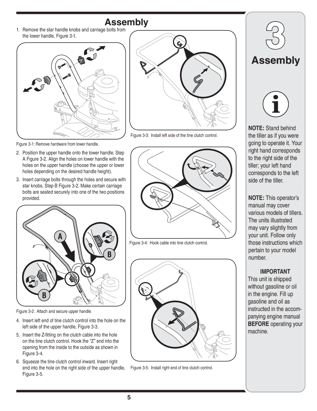
1. Remove the star handle knobs and carriage bolts from |
|
the lower handle, Figure |
|
Assembly
Figure 3-3: Install left side of the tine clutch control.
Figure 3-1: Remove hardware from lower handle.
2.Position the upper handle onto the lower handle, Step A Figure
3. Insert carriage bolts through the holes and secure with star knobs, Step B Figure
A
Figure 3-4: Hook cable into tine clutch control.
B
B
Figure 3-2: Attach and secure upper handle.
4. Insert left end of tine clutch control into the hole on the left side of the upper handle, Figure 3-3.
5.Insert the
Figure
6. Squeeze the tine clutch control inward. Insert right
end into the hole on the right side of the upper handle, Figure
NOTE: Stand behind the tiller as if you were going to operate it. Your right hand corresponds to the right side of the tiller; your left hand corresponds to the left side of the tiller.
NOTE: This operator’s manual may cover various models of tillers. The units illustrated may vary slightly from your unit. Follow only those instructions which pertain to your model number.
IMPORTANT This unit is shipped without gasoline or oil in the engine. Fill up gasoline and oil as instructed in the accom- panying engine manual BEFORE operating your machine.
5