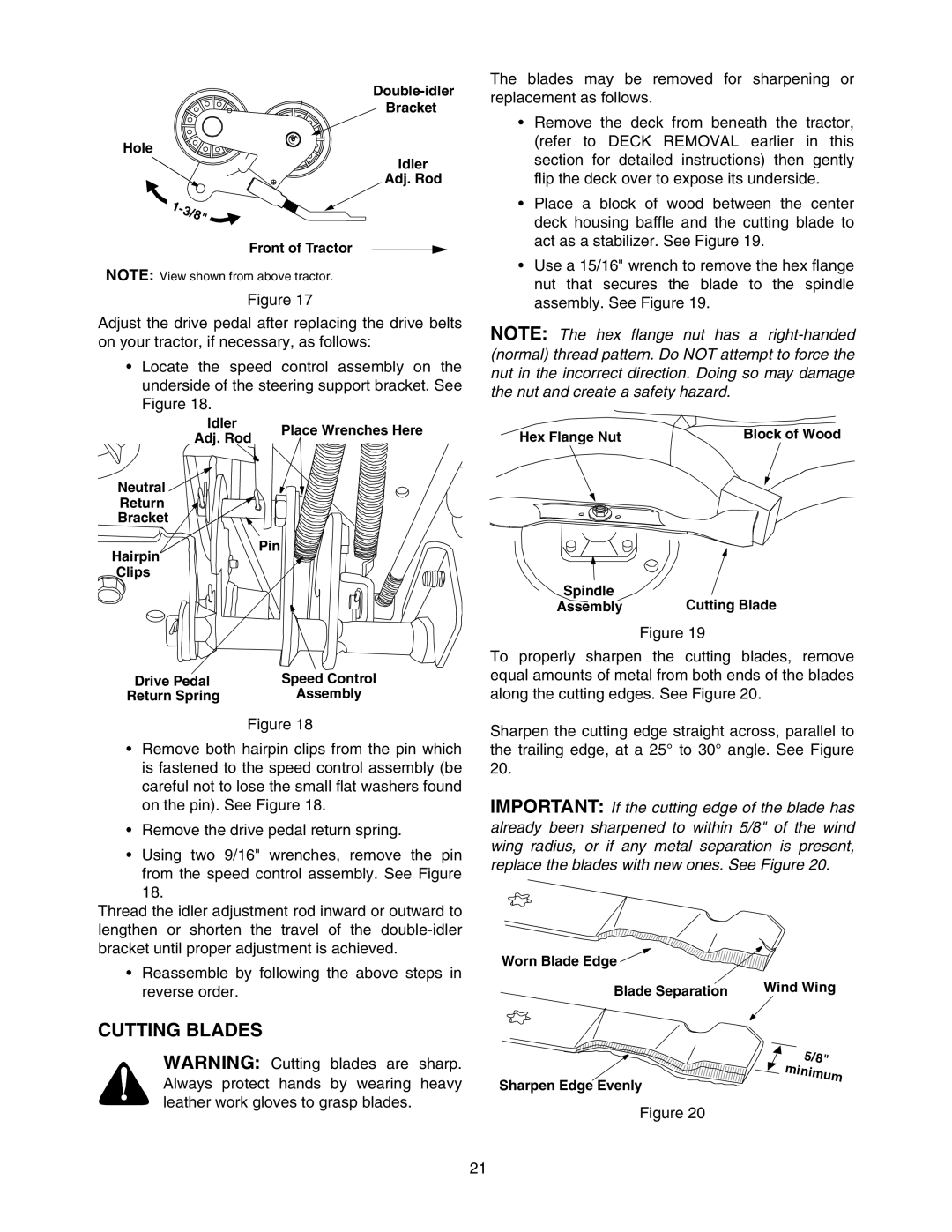
Bracket
Hole
Idler
Adj. Rod
![]()
Front of Tractor
NOTE: View shown from above tractor.
Figure 17
Adjust the drive pedal after replacing the drive belts on your tractor, if necessary, as follows:
•Locate the speed control assembly on the underside of the steering support bracket. See Figure 18.
Idler | Place Wrenches Here | |
Adj. Rod | ||
|
Neutral ![]()
![]()
![]()
Return
Bracket
Pin
Hairpin
Clips
Drive Pedal | Speed Control |
Return Spring | Assembly |
| Figure 18 |
•Remove both hairpin clips from the pin which is fastened to the speed control assembly (be careful not to lose the small flat washers found on the pin). See Figure 18.
•Remove the drive pedal return spring.
•Using two 9/16" wrenches, remove the pin
from the speed control assembly. See Figure 18.
Thread the idler adjustment rod inward or outward to lengthen or shorten the travel of the
• Reassemble by following the above steps in reverse order.
The blades may be removed for sharpening or replacement as follows.
•Remove the deck from beneath the tractor, (refer to DECK REMOVAL earlier in this section for detailed instructions) then gently flip the deck over to expose its underside.
•Place a block of wood between the center deck housing baffle and the cutting blade to act as a stabilizer. See Figure 19.
•Use a 15/16" wrench to remove the hex flange nut that secures the blade to the spindle assembly. See Figure 19.
NOTE: The hex flange nut has a
Hex Flange Nut | Block of Wood |
Spindle | Cutting Blade |
Assembly |
Figure 19
To properly sharpen the cutting blades, remove equal amounts of metal from both ends of the blades along the cutting edges. See Figure 20.
Sharpen the cutting edge straight across, parallel to the trailing edge, at a 25° to 30° angle. See Figure 20.
IMPORTANT: If the cutting edge of the blade has already been sharpened to within 5/8" of the wind wing radius, or if any metal separation is present, replace the blades with new ones. See Figure 20.
Worn Blade Edge ![]()
Blade Separation | Wind Wing |
CUTTING BLADES
WARNING: Cutting blades are sharp. Always protect hands by wearing heavy leather work gloves to grasp blades.
Sharpen Edge Evenly
Figure 20
5/8" ![]() minimum
minimum
21