Auger | Drive Belt |
| |
Belt | Drive |
| Pulley |
Idler |
|
Pulley |
|
| Engine |
| Pulley |
| Idler |
| Pulley |
Figure 26
•Reassemble auger drive belt(s) by following instructions in reverse order.
Drive Belt
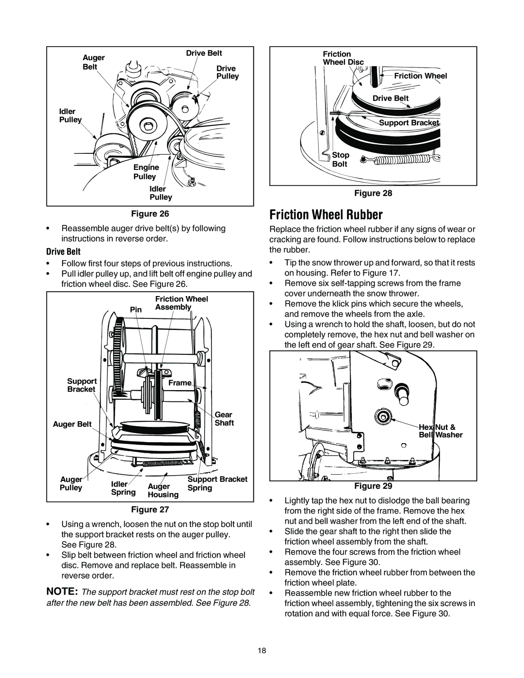
Friction
Wheel Disc
![]() Friction Wheel
Friction Wheel
Drive Belt
![]() Support Bracket
Support Bracket
Stop
Bolt
Figure 28
Friction Wheel Rubber
Replace the friction wheel rubber if any signs of wear or cracking are found. Follow instructions below to replace the rubber.
• Follow first four steps of previous instructions. | • Tip the snow thrower up and forward, so that it rests | |||||
• Pull idler pulley up, and lift belt off engine pulley and | on housing. Refer to Figure 17. | |||||
friction wheel disc. See Figure 26. | • Remove six | |||||
|
|
| Friction Wheel | cover underneath the snow thrower. | ||
|
|
| • Remove the klick pins which secure the wheels, | |||
|
| Pin | Assembly | |||
|
| and remove the wheels from the axle. | ||||
|
|
|
| |||
|
|
|
|
| ||
|
|
|
|
| • Using a wrench to hold the shaft, loosen, but do not | |
|
|
|
|
| completely remove, the hex nut and bell washer on | |
|
|
|
|
| the left end of gear shaft. See Figure 29. | |
Support |
|
| Frame |
| ||
Bracket |
|
|
|
|
| |
|
|
|
| Gear |
| |
Auger Belt |
|
|
| Shaft | Hex Nut & | |
|
|
|
|
| ||
|
|
|
|
| Bell Washer | |
Auger | Idler |
| Auger | Support Bracket | Figure 29 | |
Pulley |
| Spring | ||||
| Spring | Housing |
| • Lightly tap the hex nut to dislodge the ball bearing | ||
|
|
|
| |||
|
| Figure 27 |
| |||
|
|
| from the right side of the frame. Remove the hex | |||
• Using a wrench, loosen the nut on the stop bolt until | nut and bell washer from the left end of the shaft. | |||||
• Slide the gear shaft to the right then slide the | ||||||
the support bracket rests on the auger pulley. | ||||||
friction wheel assembly from the shaft. | ||||||
See Figure 28. |
|
|
| |||
|
|
| • Remove the four screws from the friction wheel | |||
• Slip belt between friction wheel and friction wheel | ||||||
assembly. See Figure 30. | ||||||
disc. Remove and replace belt. Reassemble in | ||||||
• Remove the friction wheel rubber from between the | ||||||
reverse order. |
|
|
| |||
|
|
| friction wheel plate. | |||
NOTE: The support bracket must rest on the stop bolt | ||||||
• Reassemble new friction wheel rubber to the | ||||||
after the new belt has been assembled. See Figure 28. | friction wheel assembly, tightening the six screws in | |||||
|
|
|
|
| rotation and with equal force. See Figure 30. | |
|
|
|
|
| 18 | |