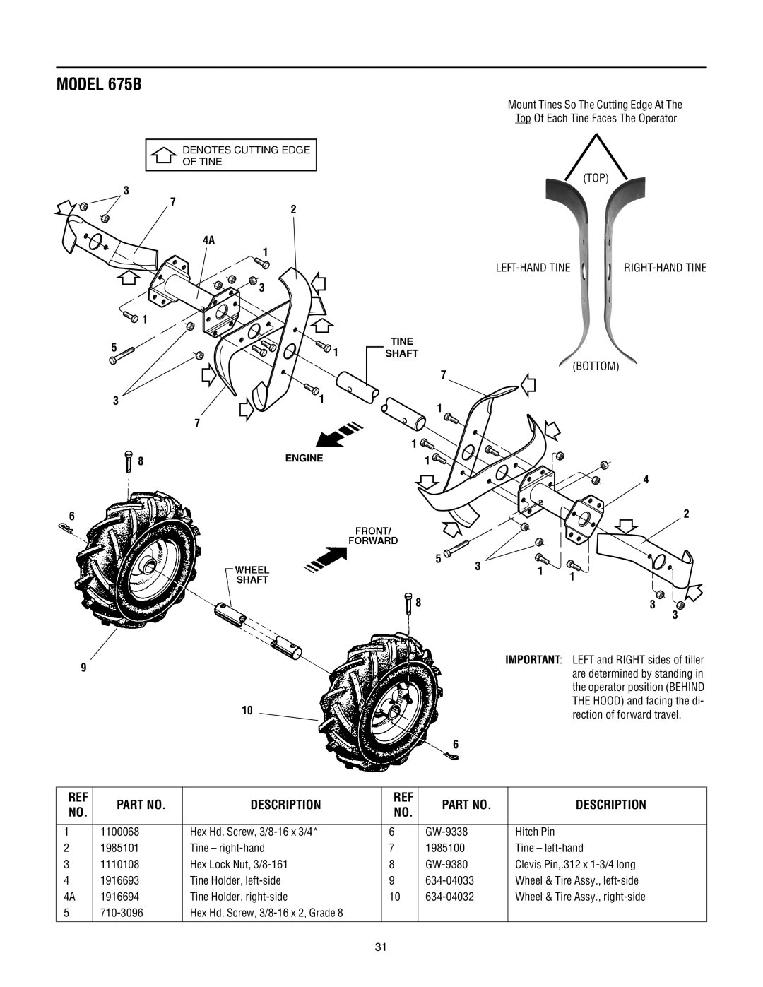
MODEL 675B
![]() DENOTES CUTTING EDGE
DENOTES CUTTING EDGE
OF TINE
3
|
|
|
| 7 | 2 |
|
|
|
|
| |||||
|
|
|
|
|
|
|
|
|
| ||||||
|
|
|
|
|
| 4A | |||||||||
|
|
|
|
| 1 |
|
|
|
|
| |||||
|
|
|
|
| 3 |
|
|
|
|
| |||||
|
|
|
|
|
|
|
|
|
| ||||||
1 |
|
|
|
|
|
| |||||||||
|
|
|
|
|
| ||||||||||
|
|
|
|
|
|
|
|
|
|
|
| ||||
|
|
|
|
|
|
|
|
|
|
|
| ||||
5 |
|
|
|
|
|
|
|
|
|
|
|
|
|
|
|
|
|
|
| 1 | |||||||||||
|
|
|
|
| |||||||||||
3 |
|
|
|
| 7 |
|
|
| 1 |
|
|
| |||
|
|
|
|
|
|
|
|
|
|
| |||||
|
|
|
|
|
|
|
|
|
|
| |||||
|
|
|
|
|
|
|
|
|
|
| |||||
8 |
|
|
|
|
| ENGINE | |||||||||
|
|
|
|
| |||||||||||
|
| ||||||||||||||
|
|
|
|
|
| ||||||||||
6
9
10
Mount Tines So The Cutting Edge At The
Top Of Each Tine Faces The Operator
(TOP)
|
TINE
SHAFT
(BOTTOM)
7
1
1 ![]() 1
1 ![]()
![]()
4
2
| 5 | 3 | 1 |
|
|
|
|
|
|
| |||
|
|
|
| |||
|
|
|
| |||
8 |
| 1 |
|
| ||
|
|
|
| |||
|
|
|
|
| ||
|
|
| 3 | |||
3
IMPORTANT: LEFT and RIGHT sides of tiller are determined by standing in the operator position (BEHIND THE HOOD) and facing the di- rection of forward travel.
6
REF | PART NO. | DESCRIPTION | REF | PART NO. | DESCRIPTION | |
NO. | NO. | |||||
|
|
|
| |||
|
|
|
|
|
| |
1 | 1100068 | Hex Hd. Screw, | 6 | Hitch Pin | ||
2 | 1985101 | Tine – | 7 | 1985100 | Tine – | |
3 | 1110108 | Hex Lock Nut, | 8 | Clevis Pin,.312 x | ||
4 | 1916693 | Tine Holder, | 9 | Wheel & Tire Assy., | ||
4A | 1916694 | Tine Holder, | 10 | Wheel & Tire Assy., | ||
5 | Hex Hd. Screw, |
|
|
| ||
|
|
|
|
|
|
31