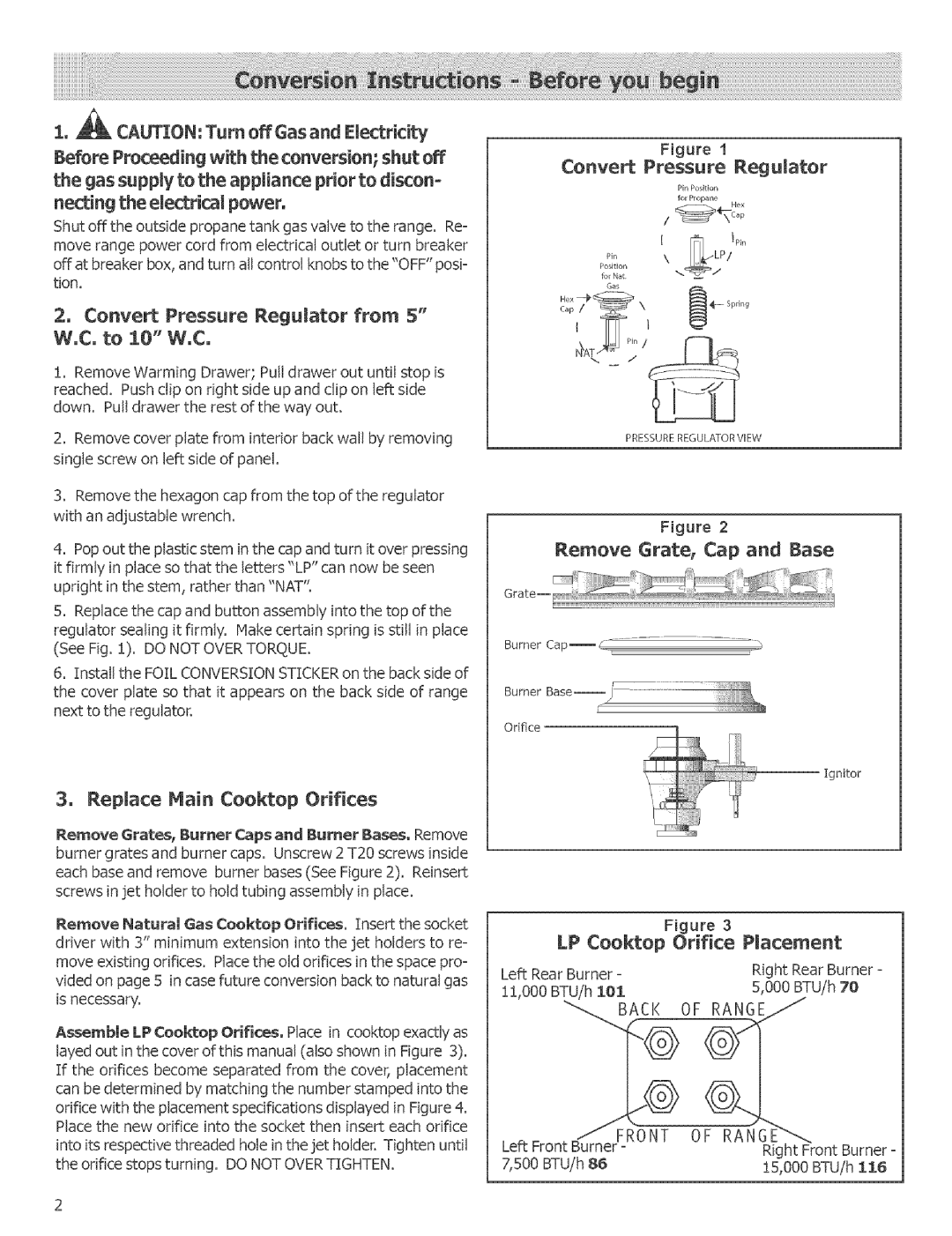
HGS252UC, HGS242UC, HGS236UC, HGS232UC, HGS245UC specifications
Bosch is renowned for producing high-quality appliances that combine functionality with modern design, and their lineup of gas ranges, namely the HGS246UC, HGS256UC, HGS247UC, HGS255UC, and HGS245UC, exemplifies this dedication. Each model is crafted with precision to cater to the needs of a contemporary kitchen while ensuring efficiency and ease of use.The Bosch HGS246UC is a 24-inch gas range that stands out for its sleek design and performance. It features four gas burners, including a powerful 18,000 BTU burner, offering rapid boiling and precise cooking control. The continuous cast-iron grates provide excellent stability for pots and pans, allowing for easy repositioning while cooking. The stainless steel finish not only adds elegance but is also resistant to fingerprints, making maintenance simpler.
The HGS256UC model expands on the features of the HGS246UC with additional cooking capacity and versatility. With five burners, it includes a specialized simmer burner that enables gentle heat for delicate sauces. The oven is equipped with European convection technology, ensuring even baking results. The dual fuel option enhances the cooking experience, allowing users to enjoy the precise temperature control of gas while benefiting from electric baking performance.
In contrast, the HGS247UC offers similar features to the HGS246UC but includes a built-in stovetop griddle. This addition allows for preparing a variety of foods simultaneously, making it ideal for family meals or entertaining guests. With its innovative design, the HGS247UC also features a 2-hour self-clean cycle, streamlining the cleaning process.
The HGS255UC presents a combination of style and functionality, prioritizing user-friendliness with its intuitive control panel. It boasts a large oven capacity and a removable oven bottom for effortless cleaning. Its sleek burner design ensures cooking is both efficient and aesthetically pleasing, further confirming Bosch's commitment to quality.
Lastly, the HGS245UC model is designed for those seeking an energy-efficient option without compromising performance. It offers precise flame control and durable construction. Its compact size is perfect for smaller kitchens while still providing ample cooking capacity.
In conclusion, Bosch's HGS gas range models encompass a range of features and technologies designed to elevate the culinary experience. From powerful burners to convection baking and easy-clean surfaces, these appliances are not only built for performance but also designed to harmonize with modern kitchen aesthetics. Each model reflects Bosch’s commitment to quality, innovation, and user satisfaction, making them a prime choice for both aspiring home cooks and seasoned chefs alike.

