Intellivox DDC Installation Manual Installation Guide | EN 10 |
|
|
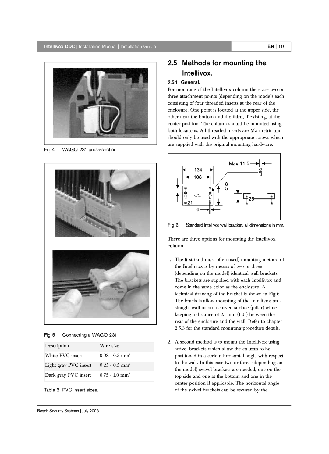
Fig 4 WAGO 231 cross-section
Fig 5 Connecting a WAGO 231
Description |
| Wire size |
|
|
|
White PVC insert |
| 0.08 - 0.2 mm2 |
|
|
|
Light gray PVC insert |
| 0.25 - 0.5 mm2 |
|
|
|
Dark gray PVC insert |
| 0.75 - 1.0 mm2 |
|
|
|
Table 2 PVC insert sizes.
2.5 Methods for mounting the
Intellivox.
2.5.1 General.
For mounting of the Intellivox column there are two or three attachment points (depending on the model) each consisting of four threaded inserts at the rear of the enclosure. One point is located at the upper side, the other near the bottom and the third, if existing, at the center position. The column should be mounted using both locations. All threaded inserts are M5 metric and should only be used with the appropriate screws which are supplied with the original mounting hardware.
Fig 6 | Standard Intellivox wall bracket, all dimensions in mm. |
There are three options for mounting the Intellivox column.
1.The first (and most often used) mounting method of the Intellivox is by means of two or three (depending on the model) identical wall brackets. The brackets are supplied with each Intellivox and come in the same color as the enclosure. A technical drawing of the bracket is shown in Fig 6. The brackets allow mounting of the Intellivox on a straight wall or on a curved surface (pillar) while keeping a distance of 25 mm (1.0”) between the rear of the enclosure and the wall. Refer to chapter 2.5.3 for the standard mounting procedure details.
2.A second method is to mount the Intellivox using swivel brackets which allow the column to be positioned in a certain horizontal angle with respect to the wall. In this case two or three (depending on the model) swivel brackets are needed, one on the top side and one at the bottom and one in the center position if applicable. The horizontal angle of the swivel brackets can be secured by the
Bosch Security Systems July 2003