LTC 8557 Series Instruction Manual Installation | EN 7 |
|
|
4INSTALLATION
ATTENTION: Installation should be performed by qualified service personnel only in accordance with the National Electrical Code or applicable local codes.
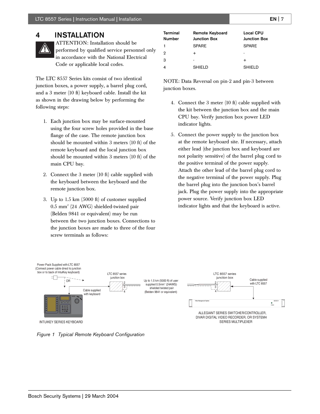
The LTC 8557 Series kits consist of two identical junction boxes, a power supply, a barrel plug cord, and a 3 meter (10 ft) keyboard cable. Install the kit as shown in the drawing below by performing the following steps:
1.Each junction box may be
2.Connect the 3 meter (10 ft) cable supplied with the keyboard between the keyboard and the remote junction box.
3.Up to 1.5 km (5000 ft) of customer supplied 0.5 mm2 (24 AWG)
Terminal | Remote Keyboard | Local CPU |
Number | Junction Box | Junction Box |
1 | SPARE | SPARE |
2 | + | - |
3 | - | + |
4 | SHIELD | SHIELD |
NOTE: Data Reversal on
4.Connect the 3 meter (10 ft) cable supplied with the kit between the junction box and the main CPU bay. Verify junction box power LED indicator lights.
5.Connect the power supply to the junction box at the remote keyboard site. If necessary, attach either lead (the junction box and keyboard are not polarity sensitive) of the barrel plug cord to the positive terminal of the power supply. Attach the other lead of the barrel plug cord to the negative terminal of the power supply. Plug the barrel plug into the junction box's barrel jack. Plug the power supply into the appropriate power source. Verify junction box LED indicator lights and that the keyboard is active.
Power Pack Supplied with LTC 8557 |
|
|
| ||
(Connect power cable direct to junction |
|
|
| ||
box or to back of IntuiKey keyboard) |
| LTC 8557 series |
| ||
|
|
|
|
| |
|
| OR |
| junction box | Up to 1.5 km (5000 ft) of user |
|
|
| 2 | ||
|
|
|
| supplied 0.5mm2 (24AWG) | |
|
|
| Cable supplied | 3 | shielded twisted pair |
|
|
| 4 | ||
|
|
| (Belden 9841 or equivalent) | ||
|
|
| with keyboard | ||
|
| BOSCH |
|
| |
|
|
|
|
| |
Prod |
| Mon |
|
|
|
Clr |
| Shot |
|
|
|
1 | 2 | 3 |
|
|
|
4 | 5 | 6 |
|
|
|
7 | 8 | 9 |
|
|
|
0 |
|
|
|
|
|
LTC 8557 series |
| |
junction box | Cable supplied | |
2 | ||
with LTC 8557 | ||
3 |
| |
4 |
| |
Video Management System | BOSCH | |
| POWER |
ALLEGIANT SERIES SWITCHER/CONTROLLER, DIVAR DIGITAL VIDEO RECORDER, OR SYSTEM4
INTUIKEY SERIES KEYBOARD | SERIES MULTIPLEXER |
Figure 1 Typical Remote Keyboard Configuration
Bosch Security Systems 29 March 2004