LTC 9449 Series Instruction Manual Camera & Lens Settings | EN 11 |
|
|
6CAMERA & LENS SETTINGS
6.1Backlight Compensation, White Balance, Line Lock, and Phase Settings
As received, the unit will be set with the backlight compensation off, the white balance on, and the line lock on. See FIGURE 6a or 6b (depending on the supplied camera) for location of the dip switches and the phase control. See FIGURE 7 for a detailed view. Note that white balance applies to color cameras only.
1.Dip Switches: The dipswitches may be changed from their default positions if desired. Remove the lens connector on black cameras to access the dip switches.
2.Phase Control: The phase may be adjusted as required by using a small blade screwdriver.
See Detail
Figure 6a: Location of Camera & Lens Settings; White Camera
Phase Control Opening
Lens Connector | See Detail |
Figure 6b: Location of Camera & Lens Settings; Black Camera
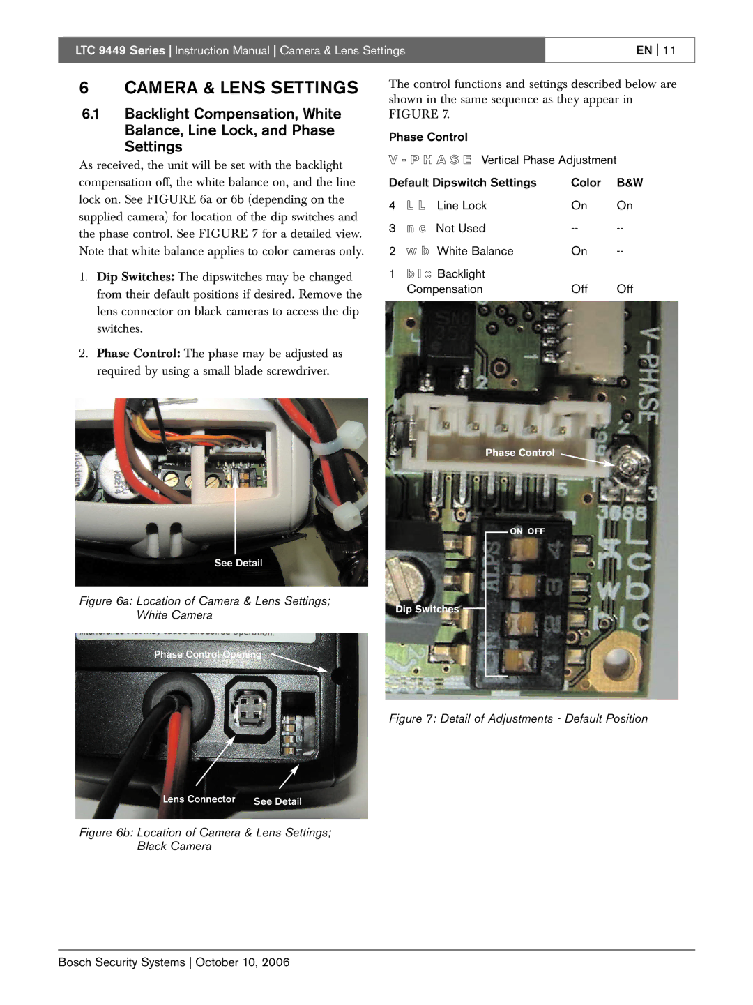
The control functions and settings described below are shown in the same sequence as they appear in FIGURE 7.
Phase Control
V - P H A S E Vertical Phase Adjustment
Default Dipswitch Settings | Color | B&W | ||
4 | L L | Line Lock | On | On |
3 | n c | Not Used | ||
2 | w b White Balance | On | ||
1 | b l c | Backlight |
|
|
| Compensation | Off | Off | |
Phase Control
ON OFF
Dip Switches
Figure 7: Detail of Adjustments - Default Position
Bosch Security Systems October 10, 2006