BM 1609929H54
Functional Description and Specifications
!WARNING Disconnect the plug from the power source before making any assembly, adjustments or changing accessories. Such preventive safety
measures reduce the risk of starting the tool accidentally.
Angle Grinders
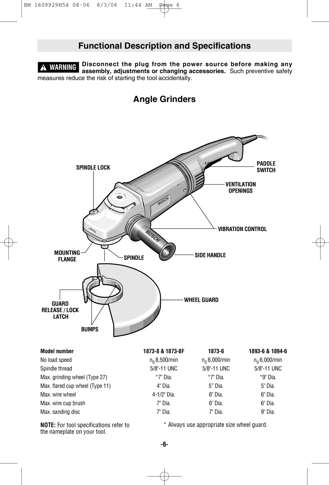
SPINDLE LOCK | PADDLE | |
SWITCH | ||
| ||
| VENTILATION | |
| OPENINGS |
VIBRATION CONTROL
MOUNTING | SPINDLE | SIDE HANDLE | |
FLANGE | |||
|
|
|
|
|
|
|
|
| WHEEL GUARD |
| |
GUARD |
|
|
|
|
|
|
|
| ||
RELEASE / LOCK |
|
|
|
|
| |||||
LATCH |
|
|
|
|
| |||||
| BUMPS |
|
|
|
|
| ||||
Model number | ||||||||||
No load speed | n0 8,500/min | n0 6,000/min | n0 6,000/min | |||||||
Spindle thread | ||||||||||
Max. grinding wheel (Type 27) | *7" Dia. | *7" Dia. | *9" Dia. | |||||||
Max. flared cup wheel (Type 11) | 4" Dia. | 5” Dia. | 5" Dia. | |||||||
Max. wire wheel | 6" Dia. | 6" Dia. | ||||||||
Max. wire cup brush | 7" Dia. | 6" Dia. | 6" Dia. | |||||||
Max. sanding disc | 7" Dia. | 7" Dia. | 9" Dia. | |||||||
NOTE: For tool specifications refer to the nameplate on your tool.
* Always use appropriate size wheel guard.