6.0WIRING

Only apply power after all connections have been made and inspected.

CAUTION

Slide the Remote Indicator Connector over the pins just to the right of the receiver’s terminal strip.

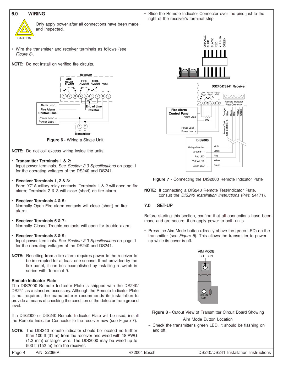
Wire the transmitter and receiver terminals as follows (see Figure 6).

NOTE: Do not install on verified fire circuits.


Receiver


AUX.


FIRE TRBL

RELAY


ALARM


ALARM ALARM VDC

DS240/DS241 Receiver

Alarm Loop

Fire Alarm Control Panel

Power Loop – Power Loop +

– +

1

2

3

4

5

6

7

8

9

End of Line

resistor

12

– +

Transmitter

Fire Alarm

Control Panel

Alarm Loop

Power Loop –

Power Loop +


Fire

Trouble 10 to 32


Alarm

Alarm

VDC


+

Remote Indicator

4

5

6

7

8

9

Plate Connector


EOL


Figure 6 - Wiring a Single Unit

NOTE: Do not coil excess wiring inside the units.

Transmitter Terminals 1 & 2:

Input power terminals. See Section 2.0 Specifications on page 1 for the operating voltages of the DS240 and DS241.


DIS2000


Voltage Monitor

Violet


Black


Ground (–)


Red


Red LED


Yellow


Yellow LED


Green


Green LED


Receiver Terminals 1, 2 & 3:

Form "C" Auxiliary relay contacts. Terminals 1 & 2 will open on fire alarm; Terminals 2 & 3 will close (short) on fire alarm.

Receiver Terminals 4 & 5:

Normally Open Fire alarm contacts will close (short) on fire alarm.

Receiver Terminals 6 & 7:

Normally Closed Trouble contacts will open for trouble alarm.

Receiver Terminals 8 & 9:

Input power terminals. See Section 2.0 Specifications on page 1 for the operating voltages of the DS240 and DS241.

Figure 7 - Connecting the DIS2000 Remote Indicator Plate

NOTE: If connecting a DIS240 Remote Test/Indicator Plate, consult the DIS240 Installation Instructions (P/N: 24171).

7.0SET-UP

Before starting this section, confirm that all connections have been made and are secure, then apply power to both units.

Press the Aim Mode button (directly above the green LED) on the transmitter (see Figure 8). This allows the transmitter to power up while its cover is off.

AIM MODE

NOTE: Resetting from a fire alarm requires power to the receiver to be interrupted for at least one second. If not provided by the fire panel, it can be accomplished by installing a switch in series with Terminal 9.

Remote Indicator Plate

The DIS2000 Remote Indicator Plate is shipped with the DS240/ DS241 as a standard accessory. Although the Remote Indicator Plate is not required, the manufacturer recommends its installation to provide a means of checking the condition of the detector from ground level.

If a DIS2000 or DIS240 Remote Indicator Plate will be used, install the Remote Indicator Connector to the receiver now (see Figure 7).

NOTE: The DIS240 remote indicator should be located no further than 100 ft (31 m) from the receiver and wired with 18 AWG (1.2 mm) or larger wire. The DIS2000 may be wired up to 500 ft (152 m) from the receiver.

BUTTON

GREEN

LED

Figure 8 - Cutout View of Transmitter Circuit Board Showing

Aim Mode Button Location

-Check the transmitter’s green LED. It should be flashing on and off.

Page 4

P/N: 22066P

© 2004 Bosch

DS240/DS241 Installation Instructions

Page 4
Image 4
Bosch Power Tools DS241, DS240 specifications Set-Up

DS240, DS241 specifications

Bosch has long been a leader in the power tool industry, renowned for its innovation and quality. Among its impressive lineup are the Bosch Power Tools DS240 and DS241, which are designed for professionals demanding durability, precision, and performance in various applications.

The Bosch DS240 and DS241 models serve as exceptional circular saws that are packed with advanced features for optimal performance. Both tools are powered by robust motors delivering high torque, ensuring that they can cut through tough materials with ease. The DS240 boasts a 15-amp motor, providing ample power for heavy-duty operations, while the DS241 is designed for lighter, more intricate tasks without sacrificing efficiency.

One of the standout features of both models is their precision cutting capabilities. Equipped with laser guide technology, the saws allow users to achieve straight cuts with enhanced accuracy. The integrated laser helps in aligning the cut line, thus reducing the risk of error, making these tools perfect for those working on detailed projects.

Another significant characteristic of the Bosch DS240 and DS241 is their ergonomic design. Both models feature soft-grip handles that ensure comfort during prolonged use, reducing hand fatigue. The lightweight construction of the saws further enhances user maneuverability, making them ideal for overhead and tight-space applications.

In terms of safety, Bosch does not compromise. Both saws feature electronic brake systems that stop the blade almost instantly when the trigger is released, preventing accidents. Additionally, they come with safety guards that minimize exposure to cutting edges, ensuring a secure operating environment.

The dual bevel capability of the DS241 allows for versatile cutting angles, making it suitable for a variety of woodworking tasks. Conversely, the DS240 focuses on robust performance for straight cuts, appealing to users who prioritize power over versatility.

Both models incorporate advanced dust extraction systems, helping to maintain clean work areas and improve visibility during cutting tasks. This feature is particularly valued by professionals working in environments where cleanliness is crucial.

Overall, the Bosch Power Tools DS240 and DS241 deliver a perfect blend of power, precision, and safety, embodying Bosch's commitment to quality and innovation in power tools. Whether tackling complex construction projects or simple home improvements, these tools stand ready to meet the demands of their users.