SERVICE PROCEDURE D24-I
Thermostat Circuit Testing
![]()
![]()
![]()
![]() DANGER
DANGER
120 volt exposure. To avoid personal injury, use caution while performing this procedure.
CAUTION |
Be Careful When Making Voltage |
Measurements or Jumping Terminals |
Not to Damage or Deform Connectors or |
Connector Pins. |
This procedure assumes the flue damper is in working order. Be sure damper opens under its own power when the thermostat circuit is
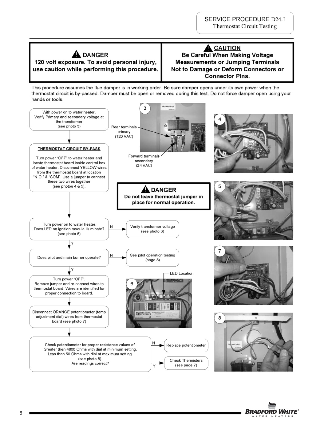
With power on to water heater,
3
Verify Primary and secondary voltage at
the transformer
(see photo 3)Rear terminals primary
(120 VAC)
THERMOSTAT CIRCUIT |
| |
Turn power “OFF” to water heater and | Forward terminals | |
secondary | ||
locate thermostat board inside control box | ||
(24 VAC) | ||
of water heater. Disconnect YELLOW wires | ||
| ||
from the thermostat board at location |
| |
“N.O.” & “COM”. Use a jumper to connect |
| |
these two wires together |
| |
(see photos 4 & 5). | DANGER | |
|
Do not leave thermostat jumper in
place for normal operation.
Turn power on to water heater. | N | Verify transformer voltage | ||
Does LED on ignition module illuminate? | ||||
| (see photo 3) | |||
(see photo 6) |
| |||
|
| |||
| Y |
|
| |
|
|
| ||
Does pilot and main burner operate? | N | See pilot operation testing | ||
| (page 8) | |||
|
|
| ||
| Y |
|
|
|
| LED Location |
Turn power “OFF”. | 6 |
|
|
| ||
|
|
| ||||
|
|
|
| |||
Remove jumper and |
|
|
|
| ||
thermostat board. Wires are identified for |
|
|
|
|
| |
proper connection to board. |
|
|
|
|
| |
|
|
|
|
|
| |
|
|
|
|
|
|
|
Disconnect ORANGE potentiometer (temp |
|
|
|
|
| |
adjustment dial) wires from thermostat |
|
|
|
|
| |
board (see photo 7) |
|
|
|
|
| |
|
|
| N |
|
|
|
|
|
|
|
|
| |
Check potentiometer for proper resistance values of: |
| Replace potentiometer | ||||
|
| |||||
Greater then 4800 Ohms with dial at minimum setting. |
|
|
|
| ||
Less than 50 Ohms with dial at maximum setting. |
|
|
|
| ||
| (see photo 8). |
|
|
|
| Check Thermisters |
| Are readings correct? |
|
|
|
| |
|
| Y |
|
| (see page 7) | |
|
|
|
|
| ||
Page 6
4
5
7
8
6