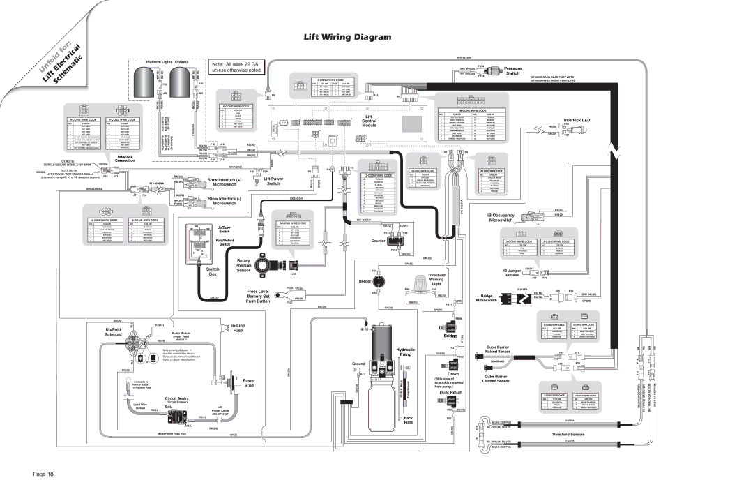
Lift Wiring Diagram


for:


Electrical


Unfold


Lift Schematic


3

2

1

1

2

3

Platform Lights (Option)

BK(18)

BK(18)


2 1


P20


J20


2 1


BK(20)

RD(20)


Note: All wires 22 GA.


BK(18)

BK(18)

unless otherwise noted.


2 1


P20


J20


6

5

4


2 1


3

2

1


BK(20)

RD(20)


6-COND WIRE CODE


8-COND WIRE CODE

8

7

6

5

NO.

COLOR

NO.

COLOR


1

RD / BK(20)

5

NOT USED


4

3

2

1

2

BU / BK(20)

6

NOT USED


3

WH / BK(20)

7

NOT USED


P6


4

GN / BK(20)

8

BK / WH(20)

P13

P5


915-4534NA

FS19

BK / WH(20)

WH / BK(20) FS18

18 17 16 15 14 13 12 11 10 9 8 7 6 5 4 3 2 1

Pressure

Switch

917-4535RNA-33 REAR PUMP LIFTS

917-4535FNA-33 FRONT PUMP LIFTS


6

5

4


4

5

6


9

8

7


7

8

9


9-COND WIRE CODE


9-COND WIRE CODE


NO.

COLOR


NO.


COLOR


1

NOT USED


1


NOT USED


2

NOT USED


2


NOT USED


3

NOT USED


3


NOT USED


4

NOT USED


4


NOT USED


5

LIFT NOT STOWED GROUND SIGNAL


5


BROWN(20)


6

GY/RD(18)VEHICLESECURE+12VINPUT


6


GRAY / RED(18)


7

LIFT STOWED +12V OUTPUT


7


BLACK(20)


8

NOT USED


8


NOT USED


9

LIFT STOWED GROUND SIGNAL


9


WHITE(20)


Interlock

GY/RD(18)


32639A

Connection

VEHICLE SECURE SIGNAL +12V INPUT


YL/LT. BU(18)


32638A


NL915IB/FIB

NL918IB/FIB

(31033A96)


NL916IB/FIB

NL917IB/FIB

NL919IB/FIB

(31033A99)

NO.

COLOR


1


RED


2


BLACK


3


WHITE


4


GREEN


54


5


NOT USED


6


NOT USED


31033A


RD(20)

P16

J16


RD(20)


1


1


BK(20)

2


2

GN(20)

BK(20)


RD(20)


WH(20)


1


1


BK(20)

2


2


P16

J16


GY/RD(18)


FS5

FS6

J9

J6

J5

J13

J3

Lift


Control


Module


J7


J4

J8


BN(20)


2

1


4

3


12

11

10

9

8

7


P4

P3

6

5

4

3

2

1


P9


4-COND WIRE CODE


18-COND WIRE CODE


NO.

COLOR

NO.


COLOR


1

RED / WHITE(20)

10


RED(20)


Interlock LED

2

BLUE / WHITE(20)

11


BLUE(20)


3

GREEN / WHITE(20)

12


GREEN(20)


FS4

4

NOT USED

13


NOT USED

PK(20)


5

ORANGE JUMPER

14


WHITE(20)


+


6

ORANGE JUMPER

15


BLACK(20)


-

7

NOT USED

16


NOT USED

GN(20)

FS7

8

ORANGE(20)

17


NOT USED


9

ORANGE / BLACK(20)

18


NOT USED


P7P8

3 2 1

6 5 4

6-COND WIRE CODE

LIFT STOWED / NOT STOWED SIGNAL

P21

J21

(Located in cavity #5, #7 or #9 - see chart above)


915-4530RNA


BK(20)


Lift Power


1 2

12-COND WIRE CODE

NO.

COLOR


COM

Stow Interlock (+)


NO.

COLOR

1

NOT USED


2

RED(20) & GREEN(20)

RD(20)

N.C.

COM.

Microswitch


RD(14)

GN(20)

4

BROWN(20)

C-H

Switch

3

NOT USED

N.O.

NO


1

ORANGE(20)

3

BLACK(20) & WHITE(20)

915-4539NA


NC


2

BLUE(20)


C5


4

NOT USED


5

WHITE(20)


NO.

COLOR

1OR(20) & OR(20)

2YELLOW(20)

3VIOLET(20)

4BLUE(20)

5BLACK(20)

6 PINK(20)


J31

P31

GN(20)


Stow Interlock (-)


6

VIOLET(20)


WH(20)

COM.


100245-001

7

NOT USED


COM


8

NOT USED


BN(20)

N.O. NO


Microswitch


9

RED(20)


NC


N.C.

C-H


10

BLACK(20)


C6


1

2

3


3

2

1


11

GREEN(20)


12

YELLOW(20)


4

5

6


6

5

4


A B C D E F


6-COND WIRE CODE

6-COND WIRE CODE


6-COND WIRE CODE

985-4532NA


NO.

COLOR

NO.


COLOR

WH


RD(20)

BK(20)

1

BLACK(20)

1

BLACK(20)


Up/Down

NO.

COLOR


OR


BK


2

FUSE HOLDER(16)

2


RED(20)


Switch

A

NOT USED


3

GREEN(20)

3

GREEN(20)


B

NOT USED


915-4533NA


BK(20)

IB Occupancy


COM.

WH(20)

COM

NO N.O.

Microswitch

4

NC


C-H

N.C.


C1


4

WHITE(20)

4

WHITE(20)


FS13

FS14

C

NOT USED


1

2

3

3

2

1

5

6

BROWN(20)

NOT USED

5

6

BROWN(20)

NOT USED


WH


Fold/Unfold

GN


RD


Switch

E

WH G


BU


L


Rotary

Position

D

E

F

ORANGE(20)

Counter

+ -

YELLOW(20)

E

BLUE(20)


FS12


GN(20)


BK(20)


OR(20)

3-COND WIRE CODE


3-COND WIRE CODE

NO.

COLOR


NO.

COLOR

1

PINK


1

BLUE(20)

2

NOT USED


2

RED(20)

3

PINK


3

GREEN(20)

Switch Sensor Box

FS1


J30

Threshold

+

Warning

Beeper

Light

-

IB Jumper Harness

32929A

J28 P28

GN(20)


Up/Fold

RL2


Solenoid


RL7


RL1

or


BK(20)


Connects to


Vehicle Battery


(+) Positive Post

32832A

RD(14)

Pump Module

Power Feed

RD(4) 26082A-4

Note polarity of diode. It must be oriented as shown. Detail at left shows two different styles of diode identification.

R 4L

Floor Level

FS20

VT(20)


Memory Set


WH(20)

Push Button


FS21


BK(20)

In-Line

Fuse

BK(20)

Power

Stud

FS8

FS9

GN(20)

GN(20)

Hydraulic

Pump

Ground

Down

RL3

Dual

Bridge


Relief


GN(14)


22166A BK(4)

PumpGround

FS5

OR(20)

YL(20)

FS17

GN(20)

FS16

Bridge

VT(20)


FS3

GN(20)

FS10

Down

(Side view of solenoids removed from pump.)

Dual Relief


31010FA

J25

P25


BU(16)


Bridge

COM

1

1

OR / BK(20)

BU(16)


Microswitch

NO


2

2

OR(20)

NC


3 2 11 2 3

3-COND WIRE CODE


3-COND WIRE CODE

NO.

COLOR


NO.

COLOR

1

YELLOW(26)


1

BLUE / WHITE(20)

2

RED(26)


2

RED / WHITE(20)

3

GREEN(26)


3

GREEN / WHITE(20)

Outer Barrier


Raised Sensor


P27

J27


32645NA60


J26

P26


Outer Barrier


Latched Sensor


1

2

3

3

2

1

3-COND WIRE CODE

3-COND WIRE CODE

BK


RD

1

2


P15


J15


12

COPPER)

GASILVER)

WH

GN

2


1


J15


P15


1


GASILVER)

COPPER)


Circuit Sentry


Lead Wire

(Circuit Breaker)


Bat.


Lift

13362A


RD(2)


Power Cable


B A T


205-0712-37


A U X

RD(2)


Aux.

BK(20)


Motor Power Feed Wire

BK(6)


Back

Plate

FS2 BU(20)

FS11

GN(20)


NO.

COLOR


NO.

COLOR


1

YELLOW(26)


1

BLUE / BLACK(20)


2

RED(26)


2

RED / BLACK(20)


3

GREEN(26)


3

GREEN / BLACK(20)


1

2

BK(24) COPPER


31221A


BK / WH(24)


P32


SILVER


Threshold Sensors


J32


BK / WH(24) SILVER


31221A


1

2

BK(24) COPPER


BK(24 GA

/ WH(24


BK

/ WH(24

BK(24 GA

BK


Page 18

Page 20
Image 20
Braun 5 service manual Lift Wiring Diagram, Electrical

5 specifications

The Braun 5 series is a standout in the realm of electric shavers, showcasing a blend of performance, comfort, and innovative technology designed for the modern man. Renowned for its ergonomic design and user-friendly features, the Braun 5 has become a reliable grooming companion for those seeking an efficient and smooth shaving experience.

One of the most notable features of the Braun 5 is its FlexMotionTec technology. This advanced system allows the shaver head to move with the curves of the face, ensuring optimal contact with the skin. This flexibility significantly reduces skin irritation while providing a thorough shave, making it particularly beneficial for individuals with sensitive skin.

The shaver's Adaptive Shaving Technology is another key characteristic. It intelligently adapts to the density of the beard hair, adjusting its power and speed accordingly. This ensures a consistent, close shave, even in challenging areas, without the need for multiple passes. The precision trimmer, located on the back of the shaver head, adds versatility, allowing for neatly defined sideburns and mustaches.

Additionally, the Braun 5 comes with a waterproof design, making it suitable for both dry and wet shaving. Users can enjoy the convenience of using gels or foams for a more comfortable glide, or simply opt for a quick, dry shave when time is of the essence. The shaver is easy to clean under running water, further enhancing its user-friendly appeal.

Battery performance is another highlight of the Braun 5 series. With a powerful Li-Ion battery, the shaver provides robust performance with up to 50 minutes of cordless shaving on a single charge. A quick 5-minute charge offers enough power for one full shave, making it a practical choice for those always on the go.

In summary, the Braun 5 series electric shaver combines precision engineering with thoughtful features aimed at delivering an exceptional shaving experience. The blend of FlexMotionTec and Adaptive Shaving Technology, coupled with its ergonomic design and robust battery life, makes the Braun 5 an indispensable tool for modern grooming. For those in search of quality, comfort, and efficiency in their daily shave, the Braun 5 stands out as a top choice in the electric shaving market.