Briggs & Stratton Power Products Automatic Transfer Switch
Installation and Owner’s Manual
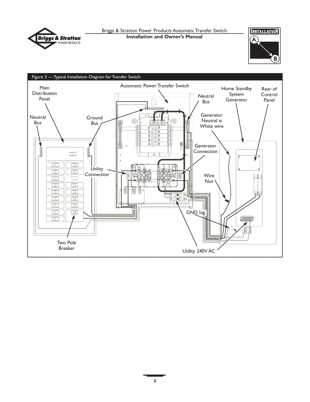
Figure 3 — Typical Installation Diagram for Transfer Switch
Main |
| Automatic Power Transfer Switch | Home Standby | Rear of | |
|
| ||||
Distribution |
|
| Neutral | System | Control |
Panel |
|
| Generator | Panel | |
|
| Bus | |||
|
|
|
|
| |
Neutral | Ground |
| Generator |
|
|
| Neutral is |
|
| ||
Bus | Bus |
|
|
| |
| White wire |
|
| ||
|
|
|
|
| |
|
|
| Generator |
|
|
|
|
| Connection |
|
|
| Utility |
|
|
|
|
| Connection |
| Wire |
|
|
|
|
| Nut |
|
|
|
| GND lug |
|
| |
| Two Pole |
|
|
|
|
| Breaker | Utility 240V AC |
|
| |
|
|
|
| ||
8
