Briggs & Stratton Power Products Home Generator
Owners Manual
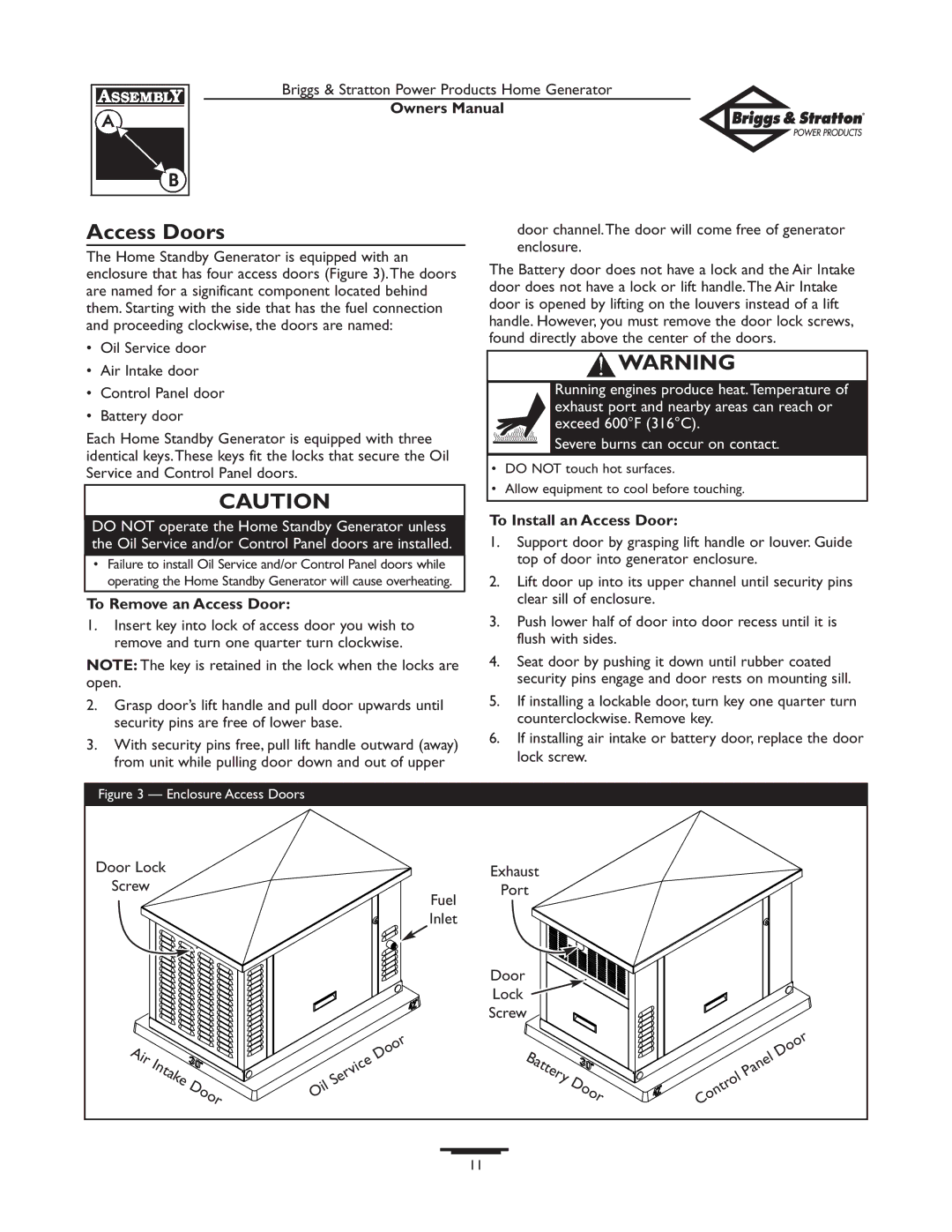
Access Doors
The Home Standby Generator is equipped with an enclosure that has four access doors (Figure 3).The doors are named for a significant component located behind them. Starting with the side that has the fuel connection and proceeding clockwise, the doors are named:
•Oil Service door
•Air Intake door
•Control Panel door
•Battery door
Each Home Standby Generator is equipped with three identical keys.These keys fit the locks that secure the Oil Service and Control Panel doors.
CAUTION
DO NOT operate the Home Standby Generator unless the Oil Service and/or Control Panel doors are installed.
•Failure to install Oil Service and/or Control Panel doors while operating the Home Standby Generator will cause overheating.
To Remove an Access Door:
1.Insert key into lock of access door you wish to remove and turn one quarter turn clockwise.
NOTE: The key is retained in the lock when the locks are open.
2.Grasp door’s lift handle and pull door upwards until security pins are free of lower base.
3.With security pins free, pull lift handle outward (away) from unit while pulling door down and out of upper
door channel.The door will come free of generator enclosure.
The Battery door does not have a lock and the Air Intake door does not have a lock or lift handle.The Air Intake door is opened by lifting on the louvers instead of a lift handle. However, you must remove the door lock screws, found directly above the center of the doors.
![]() WARNING
WARNING
Running engines produce heat.Temperature of exhaust port and nearby areas can reach or exceed 600°F (316°C).
Severe burns can occur on contact.
•DO NOT touch hot surfaces.
•Allow equipment to cool before touching.
To Install an Access Door:
1.Support door by grasping lift handle or louver. Guide top of door into generator enclosure.
2.Lift door up into its upper channel until security pins clear sill of enclosure.
3.Push lower half of door into door recess until it is flush with sides.
4.Seat door by pushing it down until rubber coated security pins engage and door rests on mounting sill.
5.If installing a lockable door, turn key one quarter turn counterclockwise. Remove key.
6.If installing air intake or battery door, replace the door lock screw.
Figure 3 — Enclosure Access Doors
Door Lock |
|
|
|
| Exhaust |
|
|
|
| |
Screw |
|
|
|
|
| Port |
|
|
|
|
|
|
|
|
|
| Fuel |
|
|
|
|
|
|
|
|
|
| Inlet |
|
|
|
|
|
|
|
|
|
| Door |
|
|
|
|
|
|
|
|
|
| Lock |
|
|
|
|
|
|
|
|
|
| Screw |
|
|
|
|
Air | Intake |
|
| Service | Door | Battery |
|
| Panel | Door |
|
|
|
|
| ||||||
|
|
|
|
|
| |||||
| Door |
|
| Door | Control |
| ||||
|
|
|
|
| ||||||
| Oil |
|
|
|
| |||||
|
|
|
|
|
|
| ||||
|
|
|
|
|
|
|
| |||
|
|
|
|
|
|
|
|
| ||
|
|
|
|
|
| 11 |
|
|
|
|