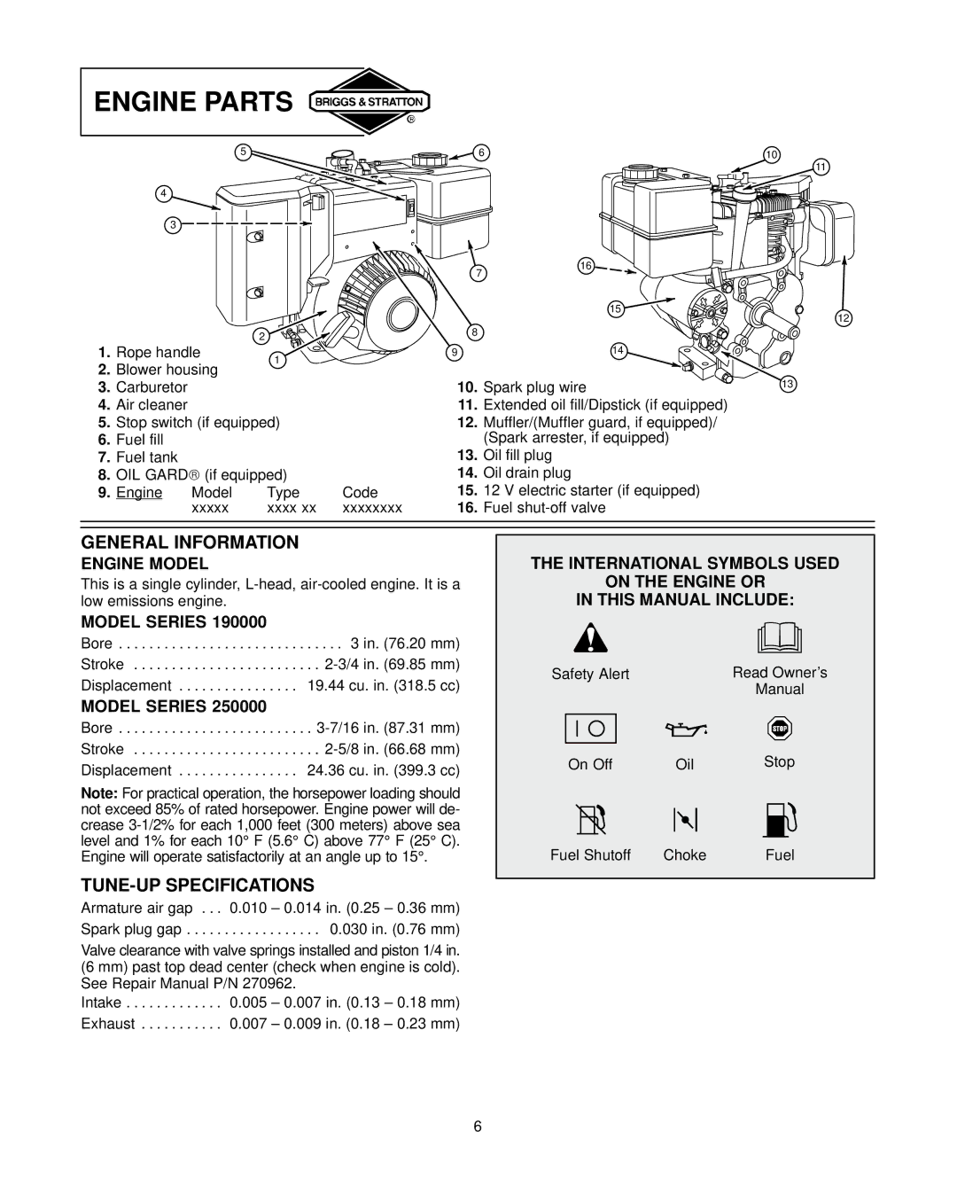
ENGINE PARTS
5
4
3 ![]()
2
1. Rope handle | 1 |
2.Blower housing
3.Carburetor
4.Air cleaner
5.Stop switch (if equipped)
6.Fuel fill
7.Fuel tank
8.OIL GARD (if equipped)
9. Engine | Model | Type | Code |
| xxxxx | xxxx xx | xxxxxxxx |
![]() 6
6
16
7
15 ![]()
8
9 | 14 |
10.Spark plug wire
11.Extended oil fill/Dipstick (if equipped)
12.Muffler/(Muffler guard, if equipped)/ (Spark arrester, if equipped)
13.Oil fill plug
14.Oil drain plug
15.12 V electric starter (if equipped)
16.Fuel
10
11
12
13
GENERAL INFORMATION
ENGINE MODEL
This is a single cylinder,
MODEL SERIES 190000
Bore . . . . . . . . . . . . . . . . . . . . . . . . . . . . . . 3 in. (76.20 mm) Stroke . . . . . . . . . . . . . . . . . . . . . . . . .
MODEL SERIES 250000
Bore . . . . . . . . . . . . . . . . . . . . . . . . . .
Note: For practical operation, the horsepower loading should not exceed 85% of rated horsepower. Engine power will de- crease
TUNE-UP SPECIFICATIONS
Armature air gap . . . 0.010 – 0.014 in. (0.25 – 0.36 mm) Spark plug gap . . . . . . . . . . . . . . . . . . 0.030 in. (0.76 mm)
Valve clearance with valve springs installed and piston 1/4 in. (6 mm) past top dead center (check when engine is cold). See Repair Manual P/N 270962.
Intake . . . . . . . . . . . . . 0.005 – 0.007 in. (0.13 – 0.18 mm) Exhaust . . . . . . . . . . . 0.007 – 0.009 in. (0.18 – 0.23 mm)
THE INTERNATIONAL SYMBOLS USED
ON THE ENGINE OR
IN THIS MANUAL INCLUDE:
Safety Alert | Read Owner’s |
| Manual |
On Off | Oil | Stop |
Fuel Shutoff | Choke | Fuel |
6
