Features and Controls
Home Generator
Read this Operator’s Manual and Safety Rules before operating your generator.
Compare the illustrations with your generator to familiarize yourself with the locations of various controls and adjustments. Save this manual for future reference.
ABC
DEFG
R |
|
|
|
|
|
P |
|
|
|
|
|
N | M | L | K | J | H |
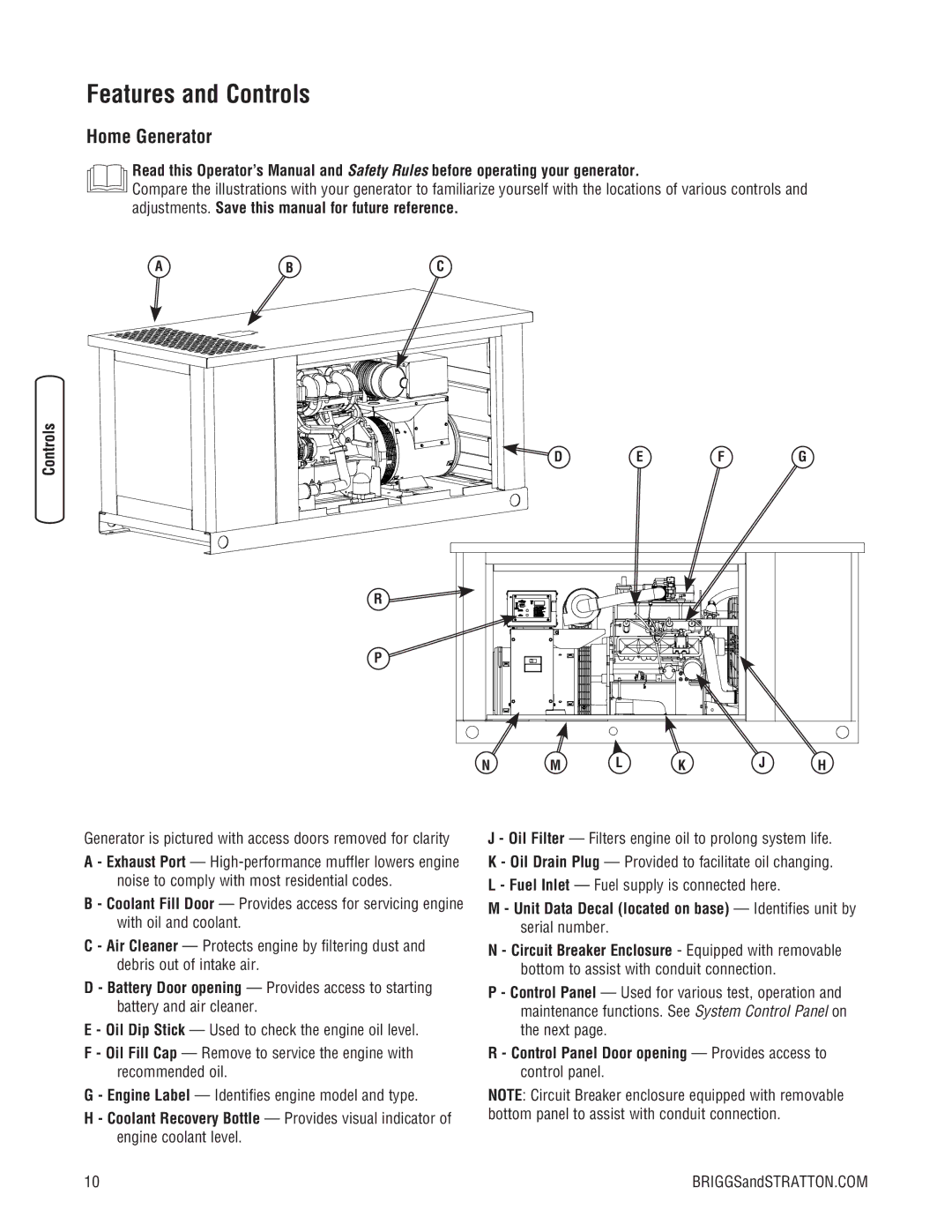
Generator is pictured with access doors removed for clarity
A - Exhaust Port —
B - Coolant Fill Door — Provides access for servicing engine with oil and coolant.
C - Air Cleaner — Protects engine by filtering dust and debris out of intake air.
D - Battery Door opening — Provides access to starting battery and air cleaner.
E - Oil Dip Stick — Used to check the engine oil level.
F - Oil Fill Cap — Remove to service the engine with recommended oil.
G - Engine Label — Identifies engine model and type.
H - Coolant Recovery Bottle — Provides visual indicator of engine coolant level.
J - Oil Filter — Filters engine oil to prolong system life. K - Oil Drain Plug — Provided to facilitate oil changing. L - Fuel Inlet — Fuel supply is connected here.
M - Unit Data Decal (located on base) — Identifies unit by serial number.
N - Circuit Breaker Enclosure - Equipped with removable bottom to assist with conduit connection.
P - Control Panel — Used for various test, operation and maintenance functions. See System Control Panel on the next page.
R - Control Panel Door opening — Provides access to control panel.
NOTE: Circuit Breaker enclosure equipped with removable bottom panel to assist with conduit connection.
10 | BRIGGSandSTRATTON.COM |