500Z 26HP - 48” Mower Deck
Tractor
Assembly
Install Ground Speed Control Levers
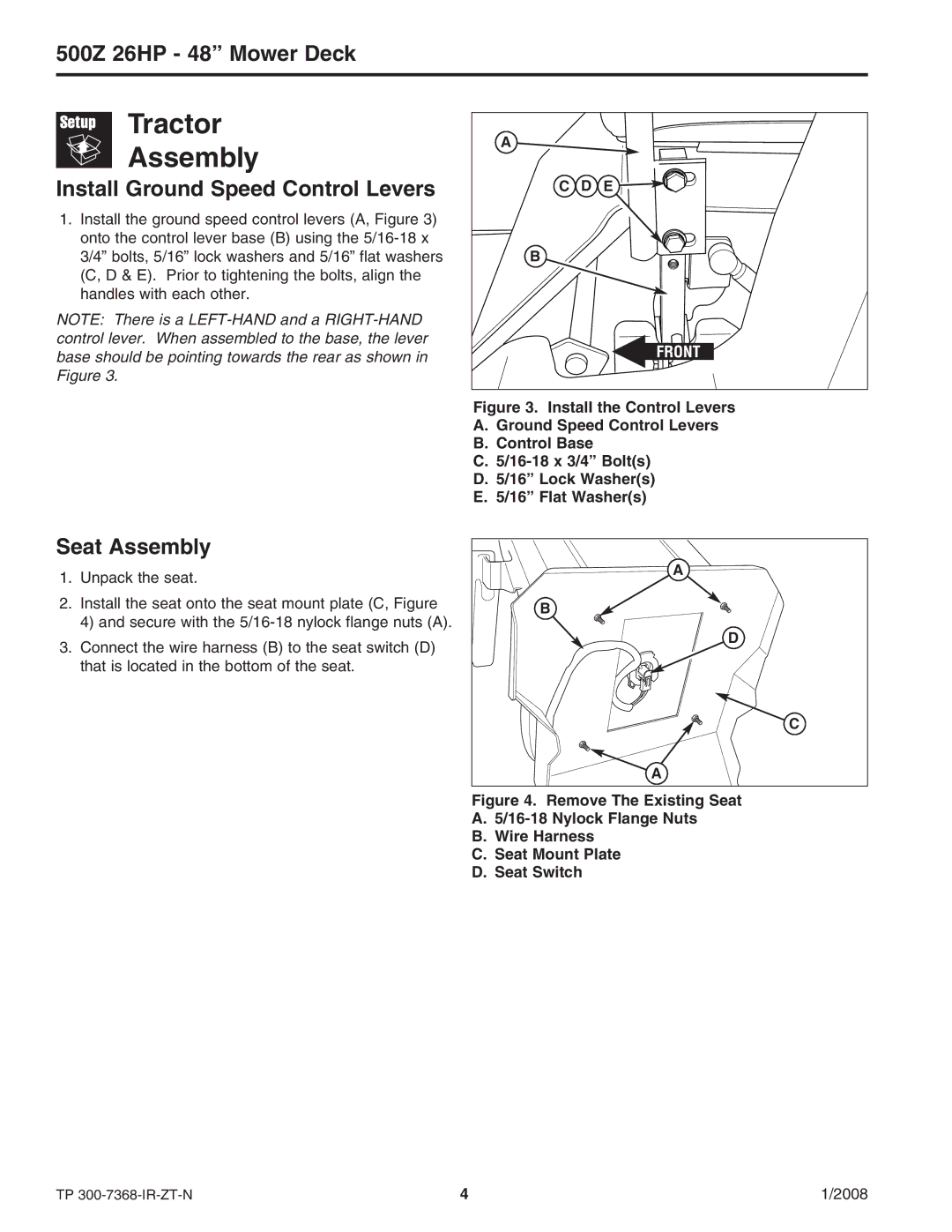
1.Install the ground speed control levers (A, Figure 3) onto the control lever base (B) using the
NOTE: There is a
A |
|
C D | E |
B |
|
Figure 3. Install the Control Levers
A.Ground Speed Control Levers
B.Control Base
C.5/16-18 x 3/4” Bolt(s)
D.5/16” Lock Washer(s)
E.5/16” Flat Washer(s)
Seat Assembly
1.Unpack the seat.
2.Install the seat onto the seat mount plate (C, Figure
4) and secure with the
3.Connect the wire harness (B) to the seat switch (D) that is located in the bottom of the seat.
A |
B |
D |
C |
A |
Figure 4. Remove The Existing Seat
A.5/16-18 Nylock Flange Nuts
B.Wire Harness
C.Seat Mount Plate
D.Seat Switch
TP | 4 | 1/2008 |