| 500Z 26HP - 48” Mower Deck | |
Parking Brake | C |
|
Adjustment | B | D |
1. Disengage the PTO, stop the engine, engage the | E |
|
parking brake, and remove the key from the ignition. |
| |
2. Raise the seat plate to gain access to the parking | A |
|
brake components. |
|
|
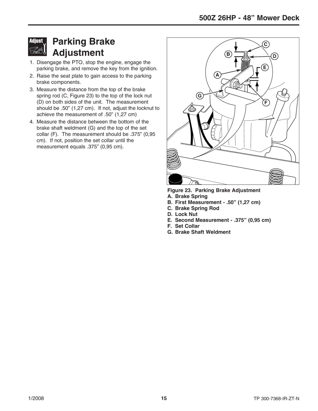
3. Measure the distance from the top of the brake |
|
|
spring rod (C, Figure 23) to the top of the lock nut | G |
|
(D) on both sides of the unit. The measurement | F |
|
should be .50” (1,27 cm). If not, adjust the locknut to |
|
|
achieve the measurement of .50” (1,27 cm) |
|
|
4. Measure the distance between the bottom of the |
|
|
brake shaft weldment (G) and the top of the set |
|
|
collar (F). The measurement should be .375” (0,95 |
|
|
cm). If not, position the set collar until the |
|
|
measurement equals .375” (0,95 cm). |
|
|
| Figure 23. Parking Brake Adjustment |
|
| A. Brake Spring |
|
| B. First Measurement |
|
| C. Brake Spring Rod |
|
| D. Lock Nut |
|
| E. Second Measurement |
|
| F. Set Collar |
|
| G. Brake Shaft Weldment |
|
1/2008 | 15 | TP |
