Installation
Continued
DECORATIVE FACING
Any noncombustible material may be used for facing (glass, tile, brick, etc.) as long as the proper clearances are observed (see Clearances, page 6). IMPORTANT: Louvered openings must not be ob- structed, and upper and lower panels must remain removable for servicing. Use only
Note: Combustible material, such as wood, that has been fireproofed is not considered noncom- bustible.
Pilot/Electrode
Assembly Adjustment
The pilot assembly is factory preset for the proper flame height. Alteration to these settings may have occurred during shipping and handling. If this is the case, some minor adjustment may be necessary and should be done by a qualified technician. To access the pilot assembly, the glass door must be opened. The proper settings for the thermopile height should be at a distance of 3/8" to 1/2" from the pilot flame as shown in Figure 52.
The electrode is installed at the factory for proper positioning. However, alterations to the position may have occurred due to shipping and handling. These settings may need adjustment and must be done by a qualified technician. The correct position and height is as shown in Figure 53.
1/8" |
|
(0.3cm) | 3/8" - 1/2" |
| |
|
Figure 52 - Correct Pilot Flame Pattern
3/4"
(19 mm)
1/2"
(12.7 mm)
Edge of Burner | Top of | |
Burner | ||
|
Figure 53 - Correct Ignitor Location
(Side View)
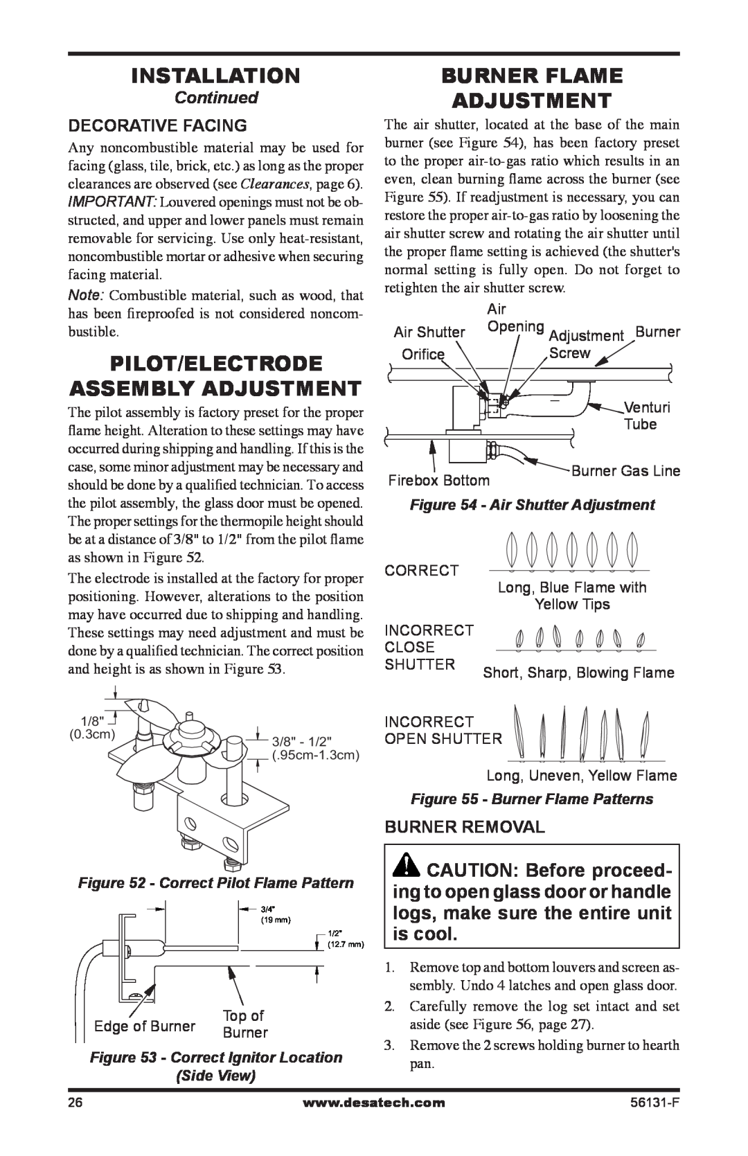
Burner Flame
Adjustment
The air shutter, located at the base of the main burner (see Figure 54), has been factory preset to the proper
| Air |
Air Shutter | Opening Adjustment Burner |
Orifice | Screw |
|
| Venturi |
|
| Tube |
Firebox Bottom | Burner Gas Line | |
| ||
Figure 54 - Air Shutter Adjustment | ||
CORRECT |
| Long, Blue Flame with |
|
| |
|
| Yellow Tips |
INCORRECT |
|
|
CLOSE |
|
|
SHUTTER | Short, Sharp, Blowing Flame | |
| ||
INCORRECT
OPEN SHUTTER
Long, Uneven, Yellow Flame
Figure 55 - Burner Flame Patterns
Burner Removal
![]() CAUTION: Before proceed- ing to open glass door or handle logs, make sure the entire unit is cool.
CAUTION: Before proceed- ing to open glass door or handle logs, make sure the entire unit is cool.
1.Remove top and bottom louvers and screen as- sembly. Undo 4 latches and open glass door.
2.Carefully remove the log set intact and set aside (see Figure 56, page 27).
3.Remove the 2 screws holding burner to hearth pan.
26 | www.desatech.com |