Venting Installation
Instructions
Continued
2. Rigid vent pipes and fittings have special | ||||
combination of pipe and elbows to the appli- | ||||
ance adaptor with pipe seams oriented towards | ||||
the wall or floor. |
|
|
|
|
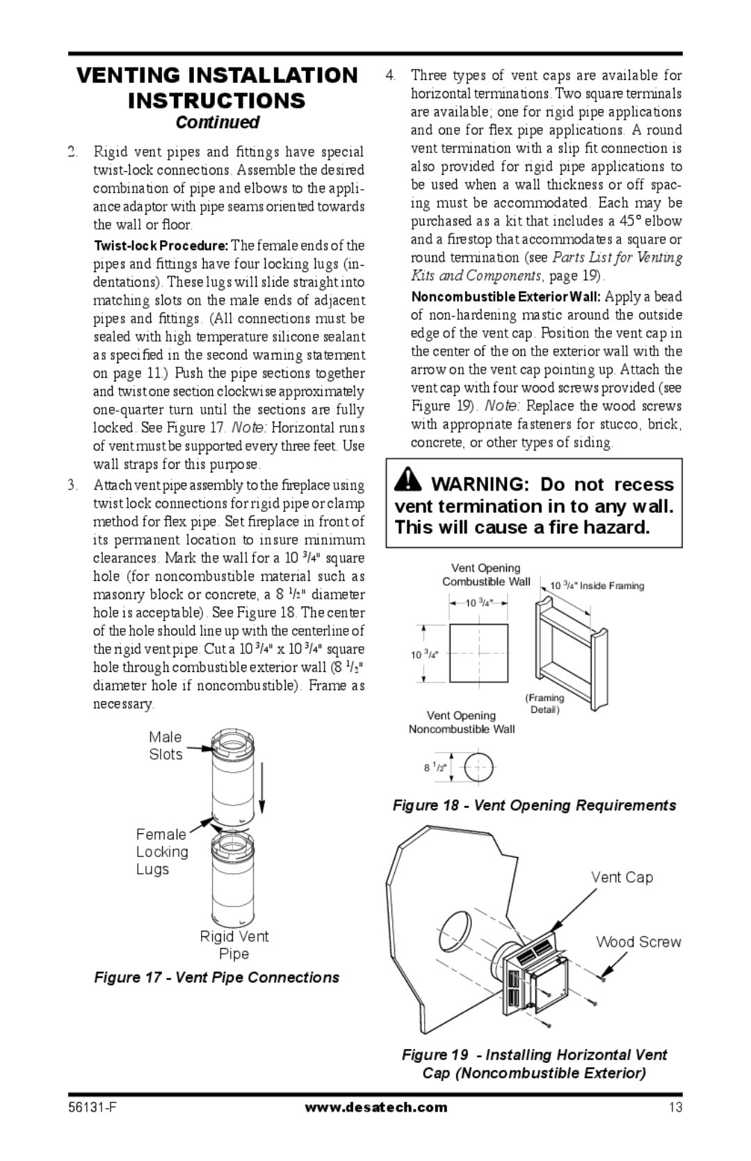
pipes and fittings have four locking lugs (in- | ||||
dentations). These lugs will slide straight into | ||||
matching slots on the male ends of adjacent | ||||
pipes and fittings. (All connections must be | ||||
sealed with high temperature silicone sealant | ||||
as specified in the second warning statement | ||||
on page 11.) Push the pipe sections together | ||||
and twist one section clockwise approximately | ||||
locked. See Figure 17. Note: Horizontal runs | ||||
of vent must be supported every three feet. Use | ||||
wall straps for this purpose. |
|
|
|
|
3. Attach vent pipe assembly to the fireplace using | ||||
twist lock connections for rigid pipe or clamp | ||||
method for flex pipe. Set fireplace in front of | ||||
its permanent location to insure minimum | ||||
clearances. Mark the wall for a 10 3/4" square | ||||
hole (for noncombustible material such as | ||||
masonry block or concrete, a 8 | 1 | 2 |
| |
| / " diameter | |||
hole is acceptable). See Figure 18. The center | ||||
of the hole should line up with the centerline of | ||||
3 | 4 |
| 3 | 4 |
the rigid vent pipe. Cut a 10 / " x 10 / " square | ||||
hole through combustible exterior wall (8 1/2" | ||||
diameter hole if noncombustible). Frame as | ||||
necessary. |
|
|
|
|
4.Three types of vent caps are available for horizontal terminations. Two square terminals are available; one for rigid pipe applications and one for flex pipe applications. A round vent termination with a slip fit connection is also provided for rigid pipe applications to be used when a wall thickness or off spac- ing must be accommodated. Each may be purchased as a kit that includes a 45° elbow and a firestop that accommodates a square or round termination (see Parts List for Venting Kits and Components, page 19).
Noncombustible Exterior Wall: Apply a bead of
![]() WARNING: Do not recess vent termination in to any wall. This will cause a fire hazard.
WARNING: Do not recess vent termination in to any wall. This will cause a fire hazard.
Vent Opening
Combustible Wall | 10 3/4" Inside Framing |
10 3/4" |
|
103/4"
(Framing
Vent Opening
Detail)
Male
Slots 

Female 

Locking
Lugs
Rigid Vent
Pipe
Figure 17 - Vent Pipe Connections
Noncombustible Wall
8 1/2"
Figure 18 - Vent Opening Requirements
Vent Cap
Wood Screw
Figure 19 - Installing Horizontal Vent
Cap (Noncombustible Exterior)
www.desatech.com | 13 |