TROUBLESHOOTING
Continued
| PROBLEM | POSSIBLE CAUSE | REMEDY | |||
| No gas to main burner when wall | 1. | Wall switch wires defec- | 1. | Check electrical connections |
|
switch and valve are set to ON |
| tive |
| and replace wall switch | ||
position |
|
|
|
|
| |
Frequent main burner outage | 1. | Burner flame is too low | 1. | Clean and adjust main burner | ||
|
| 2. | Igniter is misaligned causing | 2. | Adjust ignitor location for | |
|
|
| safety burner to "drop out" |
| maximum flame impingement | |
|
| 3. | Vent may be blocked or | 3. | on sensor | |
|
| Have vent inspected for block- | ||||
|
|
| restricted |
| age or damage | |
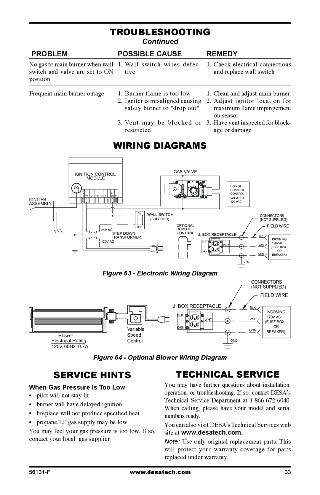
Wiring Diagrams
IGNITER ASSEMBLY
IGNITION CONTROL
MODULE
| G |
|
|
|
|
|
|
| P. |
|
|
|
| N | V2 | L1 | IND | TS | S1 |
|
|
|
| ||
| D |
| SW | V1 | ||||||||
|
|
|
|
|
|
|
|
|
|
|
|
|
|
|
|
|
|
|
|
|
|
|
|
|
|
|
|
|
|
|
|
|
|
|
|
|
|
|
ON
OFF
24V AC
STEP DOWN
TRANSFORMER
120V AC
GAS VALVE
|
| T |
|
| DO NOT |
O | I | CONNECT |
L | H |
|
|
| CONTROL |
|
| VALVE TO |
|
| 120 VAC |
WALL SWITCH | CONNECTORS |
(SUPPLIED) | (NOT SUPPLIED) |
OPTIONAL |
| FIELD WIRE | |
REMOTE |
|
| |
CONTROL J. BOX RECEPTACLE | BLK |
| |
BLK |
| INCOMING | |
| 120V AC | ||
WHT | WHT | ||
(FUSE BOX | |||
|
| ||
GRN | GRN | OR | |
| BREAKER) | ||
|
| ||
| GND |
|
Figure 63 - Electronic Wiring Diagram
CONNECTORS (NOT SUPPLIED)
FIELD WIRE
J. BOX RECEPTACLE | BLK |
|
|
|
|
|
|
|
|
|
| Variable | |
|
|
|
| ||
| Blower |
|
| Speed | |
| Electrical Rating: |
|
| Control | |
120v, 60Hz, 0.7A
BLK |
| INCOMING | |
| 120V AC | ||
WHT | WHT | ||
(FUSE BOX | |||
|
| ||
GRN | GRN | OR | |
| BREAKER) | ||
|
| ||
| GND |
|
Figure 64 - Optional Blower Wiring Diagram
Service Hints
When Gas Pressure Is Too Low
• pilot will not stay lit
• burner will have delayed ignition
• fireplace will not produce specified heat
• propane/LP gas supply may be low
You may feel your gas pressure is too low. If so, contact your local gas supplier.
Technical Service
You may have further questions about installation, operation, or troubleshooting. If so, contact DESA’s Technical Service Department at
You can also visit DESA’s Technical Services web site at www.desatech.com.
Note: Use only original replacement parts. This will protect your warranty coverage for parts replaced under warranty.
www.desatech.com | 33 |