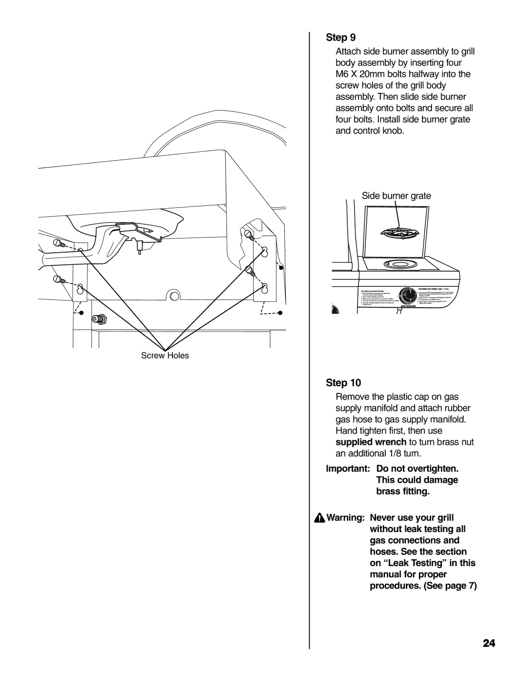
Screw Holes
Step 9
Attach side burner assembly to grill body assembly by inserting four
M6 X 20mm bolts halfway into the screw holes of the grill body assembly. Then slide side burner assembly onto bolts and secure all four bolts. Install side burner grate and control knob.
Side burner grate
|
|
| MAXIMUM SIDE BURNER LOAD = 15 lbs. | |
SIDE BURNER LIGHTING INSTRUCTIONS: | 6. If burner does NOT ignite immediately, turn control knob to | |||
1. | Read and follow all warnings and instructions | |||
| OFF, wait 5 minutes to allow gas to dissipate and repeat | |||
| in owner’s manual before lighting. |
| lighting procedure. | |
2. | Open lid before lighting side burner. | 7. Refer to owner’s manual for match lighting procedure. | ||
3. | Make sure all control knobs are in the OFF position. | 8. | For assistance, call | |
4. | Push and turn side burner control knob of that burner to HIGH. | 9. | To turn off, turn control knob clockwise until it | |
5. | Press the electronic igniter and hold for |
| locks in OFF position. | |
to light burner.
Step 10
Remove the plastic cap on gas supply manifold and attach rubber gas hose to gas supply manifold. Hand tighten first, then use supplied wrench to turn brass nut an additional 1/8 turn.
Important: Do not overtighten. This could damage brass fitting.
![]() Warning: Never use your grill without leak testing all gas connections and hoses. See the section on “Leak Testing” in this manual for proper procedures. (See page 7)
Warning: Never use your grill without leak testing all gas connections and hoses. See the section on “Leak Testing” in this manual for proper procedures. (See page 7)
24
