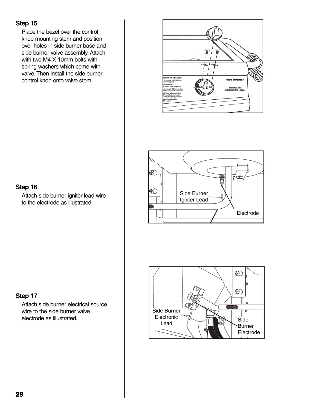
Step 15
Place the bezel over the control knob mounting stem and position over holes in side burner base and side burner valve assembly. Attach with two M4 X 10mm bolts with spring washers which come with valve. Then install the side burner control knob onto valve stem.
Step 16
Attach side burner igniter lead wire to the electrode as illustrated.
Step 17
Attach side burner electrical source wire to the side burner valve electrode as illustrated.
29
Side Burner |
| |
Igniter Lead |
| |
| Electrode | |
Side Burner |
| |
Electronic | Side | |
Lead | ||
Burner | ||
| ||
| Electrode |