HOW TO INSTALL THIS SMOKE ALARM
This unit is designed to be mounted on any standard wiring junction box up to a
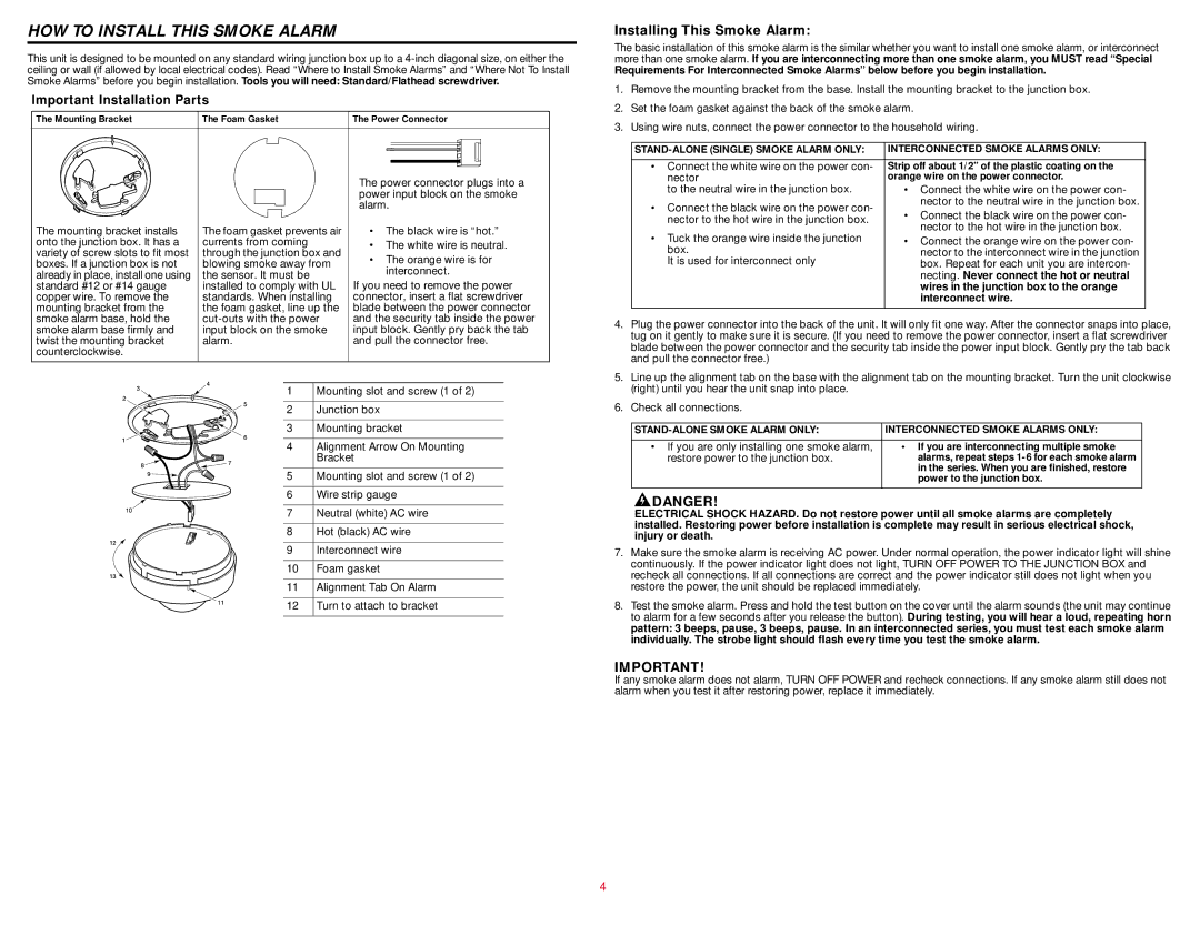
Important Installation Parts
The Mounting Bracket | The Foam Gasket | The Power Connector | |||
|
|
|
|
|
|
|
|
|
|
|
|
|
|
|
|
|
|
|
|
|
|
|
|
|
|
| The power connector plugs into a | |
|
|
| power input block on the smoke | |
|
|
| alarm. | |
The mounting bracket installs | The foam gasket prevents air | • The black wire is “hot.” | ||
onto the junction box. It has a | currents from coming |
| • The white wire is neutral. | |
variety of screw slots to fit most | through the junction box and | |||
• The orange wire is for | ||||
boxes. If a junction box is not | blowing smoke away from | |||
interconnect. | ||||
already in place, install one using | the sensor. It must be |
| ||
standard #12 or #14 gauge | installed to comply with UL | If you need to remove the power | ||
copper wire. To remove the | standards. When installing | connector, insert a flat screwdriver | ||
mounting bracket from the | the foam gasket, line up the | blade between the power connector | ||
smoke alarm base, hold the | and the security tab inside the power | |||
smoke alarm base firmly and | input block on the smoke | input block. Gently pry back the tab | ||
twist the mounting bracket | alarm. |
| and pull the connector free. | |
counterclockwise. |
|
|
| |
| 1 | Mounting slot and screw (1 of 2) | ||
| 2 | Junction box | ||
| 3 | Mounting bracket | ||
| 4 | Alignment Arrow On Mounting | ||
|
| Bracket | ||
| 5 | Mounting slot and screw (1 of 2) | ||
| 6 | Wire strip gauge | ||
| 7 | Neutral (white) AC wire | ||
| 8 | Hot (black) AC wire | ||
| 9 | Interconnect wire | ||
| 10 | Foam gasket | ||
| 11 | Alignment Tab On Alarm | ||
| 12 | Turn to attach to bracket | ||
Installing This Smoke Alarm:
The basic installation of this smoke alarm is the similar whether you want to install one smoke alarm, or interconnect more than one smoke alarm. If you are interconnecting more than one smoke alarm, you MUST read “Special
Requirements For Interconnected Smoke Alarms” below before you begin installation.
1.Remove the mounting bracket from the base. Install the mounting bracket to the junction box.
2.Set the foam gasket against the back of the smoke alarm.
3.Using wire nuts, connect the power connector to the household wiring.
INTERCONNECTED SMOKE ALARMS ONLY: | ||
|
| |
• Connect the white wire on the power con- | Strip off about 1/2” of the plastic coating on the | |
nector | orange wire on the power connector. | |
to the neutral wire in the junction box. | • Connect the white wire on the power con- | |
• Connect the black wire on the power con- | nector to the neutral wire in the junction box. | |
• Connect the black wire on the power con- | ||
nector to the hot wire in the junction box. | ||
nector to the hot wire in the junction box. | ||
• Tuck the orange wire inside the junction | ||
• Connect the orange wire on the power con- | ||
box. | nector to the interconnect wire in the junction | |
It is used for interconnect only | box. Repeat for each unit you are intercon- | |
| necting. Never connect the hot or neutral | |
| wires in the junction box to the orange | |
| interconnect wire. | |
|
|
4.Plug the power connector into the back of the unit. It will only fit one way. After the connector snaps into place, tug on it gently to make sure it is secure. (If you need to remove the power connector, insert a flat screwdriver blade between the power connector and the security tab inside the power input block. Gently pry the tab back and pull the connector free.)
5.Line up the alignment tab on the base with the alignment tab on the mounting bracket. Turn the unit clockwise (right) until you hear the unit snap into place.
6.Check all connections.
INTERCONNECTED SMOKE ALARMS ONLY: | |
|
|
• If you are only installing one smoke alarm, | • If you are interconnecting multiple smoke |
restore power to the junction box. | alarms, repeat steps |
| in the series. When you are finished, restore |
| power to the junction box. |
|
|
![]() DANGER!
DANGER!
ELECTRICAL SHOCK HAZARD. Do not restore power until all smoke alarms are completely installed. Restoring power before installation is complete may result in serious electrical shock, injury or death.
7.Make sure the smoke alarm is receiving AC power. Under normal operation, the power indicator light will shine continuously. If the power indicator light does not light, TURN OFF POWER TO THE JUNCTION BOX and recheck all connections. If all connections are correct and the power indicator still does not light when you restore the power, the unit should be replaced immediately.
8.Test the smoke alarm. Press and hold the test button on the cover until the alarm sounds (the unit may continue to alarm for a few seconds after you release the button). During testing, you will hear a loud, repeating horn pattern: 3 beeps, pause, 3 beeps, pause. In an interconnected series, you must test each smoke alarm individually. The strobe light should flash every time you test the smoke alarm.
IMPORTANT!
If any smoke alarm does not alarm, TURN OFF POWER and recheck connections. If any smoke alarm still does not alarm when you test it after restoring power, replace it immediately.
4