HD6135FB specifications
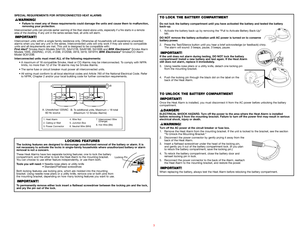
The BRK electronic HD6135FB is an advanced electronic smoke and carbon monoxide alarm designed to provide reliable safety and peace of mind to households and businesses. This state-of-the-art device combines innovative technology with user-friendly features ensuring enhanced protection against deadly smoke and toxic gases.One of the standout features of the HD6135FB is its dual sensor technology, which utilizes both photoelectric and ionization sensors. This combination allows for improved detection of different types of fires, including smoldering fires and fast-flaming fires. The photoelectric sensor effectively identifies slow-burning fires that produce large amounts of smoke, while the ionization sensor is quick to respond to fast-flaming fires. This integrated approach significantly increases the overall effectiveness and reliability of the alarm.
In addition to fire detection, the HD6135FB excels in carbon monoxide detection. CO is often referred to as the silent killer, as it is colorless and odorless, making it undetectable without a proper alarm system. The HD6135FB is equipped with a sensitive electrochemical sensor that identifies dangerous levels of carbon monoxide, ensuring timely alerts to occupants.
The alarm is designed with user convenience in mind. It features a built-in voice alarm that announces the type of danger detected, whether it’s smoke or carbon monoxide. This feature helps users swiftly identify the source of danger without confusion. Additionally, the alarm is equipped with a lithium battery backup, ensuring continuous operation during power outages and enhancing its reliability.
Installation of the HD6135FB is straightforward, with the option to be mounted on walls or ceilings. Its sleek design ensures that it blends seamlessly into any environment. The device also includes a test button for regular function checks, providing peace of mind that the unit is working correctly.
Furthermore, the HD6135FB has an advanced LED indicator that displays the status of the alarm. A green light indicates normal operation, while a red light alerts users to an active alarm condition. This visual feedback is crucial for quickly assessing the status of the device.
In summary, the BRK electronic HD6135FB smoke and carbon monoxide alarm combines dual sensor technology, reliable monitoring, and user-friendly features. Its robust design and advanced alert systems make it an essential addition to any safety plan, helping to protect lives and property from the dangers of fire and carbon monoxide exposure.

