INSTALLING THE

DUCTWORK

NOTE

THESE INSTRUCTIONS WILL FOLLOW THE PLANS MADE ON PAGE 2. START AT THE EX- TERIOR AND RUN THE DUCT BACK TO THE RANGE HOOD.

FOR BEST PERFORMANCE OF YOUR RANGE HOOD, USE THE SHORTEST POSSIBLE DUCT RUN AND A MINIMUM NUMBER OF ELBOWS.

NEVER VENT A RANGE HOOD INTO AN AT- TIC SPACE BECAUSE A BUILDUP OF GREASE WILL BECOME A FIRE HAZARD.

USE ONLY METAL DUCTWORK (DO NOT USE PLASTIC DUCT). ASSEMBLE SECURELY SO THAT IN CASE OF A GREASE FIRE ON THE RANGE, THE FIRE WILL BE CONTAINED IN- SIDE METAL DUCT WORK.

IT IS A GOOD PRACTICE TO TAPE ALL DUCT CONNECTIONS, MAKING THEM BOTH SE- CURE AND AIR TIGHT.

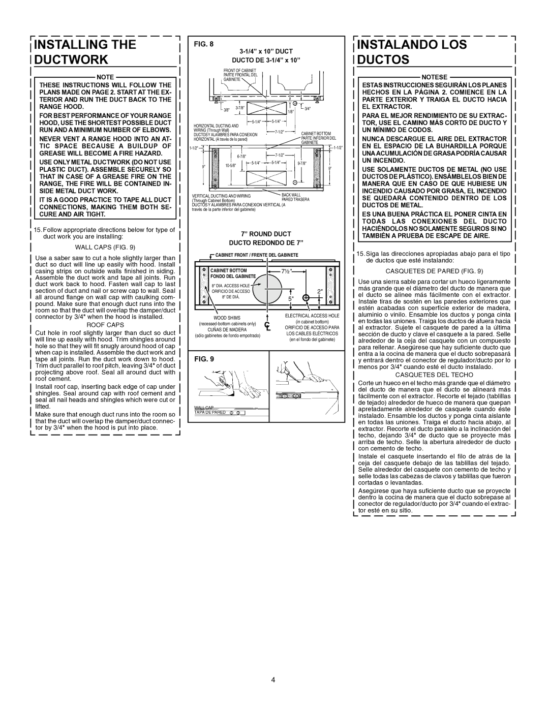
15.Follow appropriate directions below for type of duct work you are installing:

WALL CAPS (FIG. 9)

Use a saber saw to cut a hole slightly larger than duct so duct will line up easily with hood. Install casing strips on outside walls finished in siding. Assemble the duct work and tape all joints. Run duct work back to hood. Fasten wall cap to last section of duct and nail or screw cap to wall. Seal all around flange on wall cap with caulking com- pound. Make sure that enough duct runs into the room so that the duct will overlap the damper/duct connector by 3/4" when the hood is installed.

ROOF CAPS

Cut hole in roof slightly larger than duct so duct will line up easily with hood. Trim shingles around hole so that they will fit snugly around hood of cap when cap is installed. Assemble the duct work and tape all joints. Run the duct work down to hood. Trim duct parallel to roof pitch, leaving 3/4" of duct projecting above roof. Seal all around duct with roof cement.

Install roof cap, inserting back edge of cap under shingles. Seal around cap with roof cement and seal all nail heads and shingles which were cut or lifted.

Make sure that enough duct runs into the room so that the duct will overlap the damper/duct connec- tor by 3/4" when the hood is put into place.

FIG. 8

3-1/4” x 10” DUCT

DUCTO DE 3-1/4” x 10”

FRONT OF CABINET

PARTE FRONTAL DEL

GABINETE


3/8"


3-7/8"


3/4"


1/8"


HORIZONTAL DUCTING AND

5-1/4"


5-1/4"


WIRING (Through Wall)


7-1/2"


CABINET BOTTOM


DUCTOS Y ALAMBRES PARA CONEXION


HORIZONTAL (A través de la pared)


PARTE INFERIOR DEL


GABINETE

1-1/2"


1-1/2"


7-1/2"


6

-7/8"


5-1/4"


5-1/4"


9-7/8"


1

0-5/8

"


9"


BACK WALL


9"


VERTICAL DUCTING AND WIRING


(Through Cabinet Bottom)


PARED TRASERA

DUCTOS Y ALAMBRES PARA CONEXION VERTICAL (A través de la parte inferior del gabinete)

7” ROUND DUCT

DUCTO REDONDO DE 7”

CABINET FRONT / FRENTE DEL GABINETE

CABINET BOTTOM

7½"

FONDO DEL GABINETE


8" DIA. ACCESS HOLE

2"

ORIFICIO DE ACCESO

8" DE DIÁ.

5"


WOOD SHIMS

ELECTRICAL ACCESS HOLE

(in cabinet bottom)

(recessed-bottom cabinets only)

ORIFICIO DE ACCESO PARA

CUÑAS DE MADERA

LOS CABLES ELÉCTRICOS

(sólo gabinetes de fondo empotrado)

(en el fondo del gabinete)


FIG. 9

WALL CAP

TAPA DE PARED

INSTALANDO LOS

DUCTOS

NOTESE

ESTAS INSTRUCCIONES SEGUIRÁN LOS PLANES HECHOS EN LA PÁGINA 2. COMIENCE EN LA PARTE EXTERIOR Y TRAIGA EL DUCTO HACIA EL EXTRACTOR.

PARA EL MEJOR RENDIMIENTO DE SU EXTRAC- TOR, USE EL CAMINO MÁS CORTO DE DUCTO Y UN MÍNIMO DE CODOS.

NUNCA DESCARGUE EL AIRE DEL EXTRACTOR EN EL ESPACIO DE LA BUHARDILLA PORQUE UNA ACUMULACIÓN DE GRASA PODRÍA CAUSAR UN INCENDIO.

USE SOLAMENTE DUCTOS DE METAL (NO USE DUCTOS DE PLÁSTICO). ENSÁMBLELOS BIEN DE MANERA QUE EN CASO DE QUE HUBIESE UN INCENDIO CAUSADO POR GRASA, EL INCENDIO SE QUEDARÁ CONTENIDO DENTRO DE LOS DUCTOS DE METAL.

ES UNA BUENA PRÁCTICA EL PONER CINTA EN TODAS LAS CONEXIONES DEL DUCTO HACIÉNDOLOS NO SOLAMENTE SEGUROS SI NO TAMBIÉN A PRUEBA DE ESCAPE DE AIRE.

15.Siga las direcciones apropiadas abajo para el tipo de ductos que esté instalando:

CASQUETES DE PARED (FIG. 9)

Use una sierra sable para cortar un hueco ligeramente más grande que el diámetro del ducto de manera que el ducto se alinee más fácilmente con el extractor. Instale tiras de sostén en las paredes exteriores que estén acabadas con superficie exterior de madera, aluminio o vinilo. Ensamble los ductos y ponga cinta en todas las uniones. Traiga los ductos de afuera hacia al extractor. Sujete el casquete de pared a la última sección de ducto y clave el casquete a la pared. Selle alrededor de la ceja del casquete con un compuesto para rellenar. Asegúrese que hay suficiente ducto que entra a la cocina de manera que el ducto sobrepasará y entrará dentro el conector de regulador/ducto por lo menos por 3/4" cuando esté el ducto instalado.

CASQUETES DEL TECHO

Corte un hueco en el techo más grande que el diámetro del ducto de manera que el ducto se alineará más fácilmente con el extractor. Recorte el tejado (tablillas de tejado) alrededor de hueco de manera que quepan apretadamente alrededor de casquete cuando éste instalado. Ensamble los ductos y ponga cinta aislante en todas las uniones. Traiga el ducto hacia abajo, al extractor. Recorte el ducto paralelo a la inclinación del techo, dejando 3/4" de ducto que se proyecte más arriba de techo. Selle la abertura alrededor de ducto con cemento de techo.

Instale el casquete insertando el filo de atrás de la ceja del casquete debajo de las tablillas del tejado. Selle alrededor del casquete con cemento de techo y selle todas las cabezas de clavos y tablillas que fueron cortadas o levantadas.

Asegúrese que haya suficiente ducto que se proyecte dentro la cocina de manera que el ducto sobrepase al conector de regulador/ducto por 3/4" cuando el extrac- tor esté en su sitio.

4

Page 4
Image 4
Broan 46000 warranty Installing Ductwork, Instalando LOS Ductos, 4 x 10 Duct Ducto DE 3-1/4 x, Round Duct Ducto Redondo DE

46000 specifications

The Broan 46000 series is a highly regarded line of range hoods that blends performance with sleek design, making it a popular choice for modern kitchens. Designed to provide efficient ventilation and elevate the culinary experience, this series boasts an impressive range of features and technologies that enhance both functionality and aesthetics.

One of the standout features of the Broan 46000 series is its powerful ventilation capabilities. With options ranging from 250 to 400 CFM, these range hoods effectively eliminate smoke, heat, and odors, resulting in a fresher cooking environment. The advanced ventilator design ensures improved air circulation, ensuring that your kitchen remains comfortable, even during extensive cooking sessions.

In terms of operation, the Broan 46000 offers easy-to-use controls for hassle-free functionality. Most models are equipped with user-friendly push-button controls that allow you to select from multiple fan speeds and lighting options. The intuitive design ensures that you can adjust the settings quickly, even while you’re busy cooking.

Lighting is another vital aspect of the Broan 46000 series. Many models come equipped with bright, energy-efficient LED lights that illuminate your cooking surface. This provides not only better visibility for cooking tasks but also enhances the overall ambiance of your kitchen. The integrated lighting fixtures are designed to be both practical and aesthetically pleasing, further enhancing the range hood's sleek appearance.

The construction of the Broan 46000 also deserves mention. Made from durable stainless steel, these range hoods are designed to withstand the rigors of daily kitchen use while resisting corrosion and ensuring long-lasting performance. The smooth surfaces make for easy cleaning, which is a significant advantage for busy households.

Another notable characteristic of the Broan 46000 series is its versatile installation options. The hoods in this series can be installed as either under-cabinet or wall-mounted units, offering flexibility to fit various kitchen designs. This adaptability makes it easy to incorporate the range hood into any kitchen layout, enhancing both the functionality and style of the space.

In summary, the Broan 46000 series range hoods provide exceptional performance, user-friendly features, and an elegant design, making them a smart choice for any modern kitchen. With powerful ventilation, energy-efficient lighting, and durable construction, these range hoods are engineered to meet the needs of aspiring home chefs and everyday cooks alike. Whether you are renovating your kitchen or simply seeking an upgrade, the Broan 46000 series is an excellent addition that will elevate your cooking expereince.