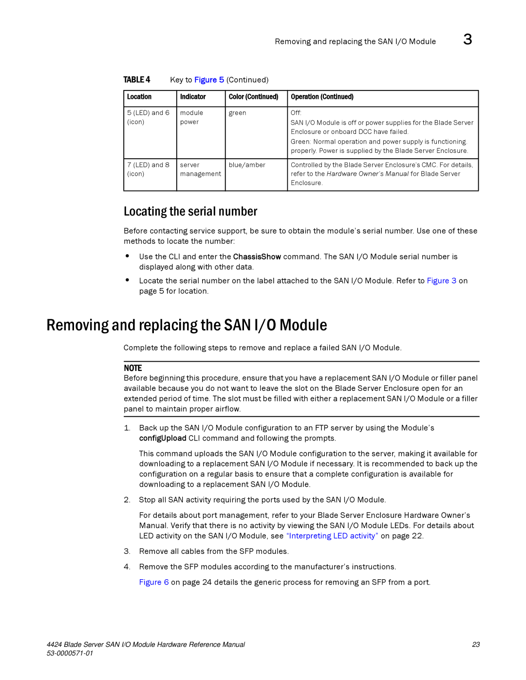
Removing and replacing the SAN I/O Module

3

TABLE 4

Key to Figure 5 (Continued)


Location


Indicator

Color (Continued)

Operation (Continued)


5 (LED) and 6


module

green

Off:


(icon)


power


SAN I/O Module is off or power supplies for the Blade Server


Enclosure or onboard DCC have failed.


Green: Normal operation and power supply is functioning.


properly. Power is supplied by the Blade Server Enclosure.


7 (LED) and 8


server

blue/amber

Controlled by the Blade Server Enclosure's CMC. For details,

(icon)


management


refer to the Hardware Owner’s Manual for Blade Server


Enclosure.


Locating the serial number

Before contacting service support, be sure to obtain the module’s serial number. Use one of these methods to locate the number:

Use the CLI and enter the ChassisShow command. The SAN I/O Module serial number is displayed along with other data.

Locate the serial number on the label attached to the SAN I/O Module. Refer to Figure 3 on page 5 for location.

Removing and replacing the SAN I/O Module

Complete the following steps to remove and replace a failed SAN I/O Module.

NOTE

Before beginning this procedure, ensure that you have a replacement SAN I/O Module or filler panel available because you do not want to leave the slot on the Blade Server Enclosure open for an extended period of time. The slot must be filled with either a replacement SAN I/O Module or a filler panel to maintain proper airflow.

1.Back up the SAN I/O Module configuration to an FTP server by using the Module’s configUpload CLI command and following the prompts.

This command uploads the SAN I/O Module configuration to the server, making it available for downloading to a replacement SAN I/O Module if necessary. It is recommended to back up the configuration on a regular basis to ensure that a complete configuration is available for downloading to a replacement SAN I/O Module.

2.Stop all SAN activity requiring the ports used by the SAN I/O Module.

For details about port management, refer to your Blade Server Enclosure Hardware Owner’s Manual. Verify that there is no activity by viewing the SAN I/O Module LEDs. For details about LED activity on the SAN I/O Module, see “Interpreting LED activity” on page 22.

3.Remove all cables from the SFP modules.

4.Remove the SFP modules according to the manufacturer’s instructions.

Figure 6 on page 24 details the generic process for removing an SFP from a port.

4424 Blade Server SAN I/O Module Hardware Reference Manual

23

53-0000571-01


Page 33
Image 33
Brocade Communications Systems 53-1000571-01 manual Removing and replacing the SAN I/O Module, Locating the serial number

53-1000571-01 specifications

Brocade Communications Systems has been a key player in the networking industry, offering a range of advanced products designed to improve data center efficiency and connectivity. One notable product is the Brocade 53-1000571-01, a versatile device that integrates modern networking technologies with user-friendly features.

The Brocade 53-1000571-01 is primarily recognized as a high-performance 16 Gbps Fibre Channel switch, designed to support the demanding requirements of both large data centers and enterprise environments. As networking needs continue to evolve, this switch provides the necessary scalability and reliability while maintaining cost-effectiveness.

One of the main features of the 53-1000571-01 is its support for both 8 Gbps and 16 Gbps Fibre Channel speeds, allowing it to accommodate various legacy systems while also preparing users for the latest high-speed data applications. This ensures that organizations can maximize their existing investments while equipping themselves for future growth.

Another significant characteristic of the Brocade 53-1000571-01 is its intelligent management capabilities. The device comes with Brocade Fabric OS, which provides advanced networking features like dynamic path optimization, automated configuration, and real-time monitoring. These capabilities help streamline network management tasks, improve operational efficiencies, and reduce the chances of human error.

Moreover, this switch is equipped with robust security features, including zoning and encrypted connections, which are crucial in protecting sensitive data within storage area networks. The Brocade 53-1000571-01 not only enhances connectivity but also provides secure and seamless data access that is vital for modern enterprises.

Its modular architecture enables seamless expansion and adaptability to meet growing data requirements. As businesses expand and storage needs surge, this switch can accommodate additional ports and connections without significant downtime or infrastructure overhaul.

In conclusion, the Brocade Communications Systems 53-1000571-01 stands out as a high-performance Fibre Channel switch that meets the diverse needs of today’s data-driven environments. Its combination of speed, intelligent management tools, robust security features, and modularity makes it a reliable choice for organizations looking to enhance their networking infrastructure and ensure future readiness.