DIMENSIONS |
| ||
(664mm) | (733mm) |
| |
| |||
| |||
|
| ||
(FLUE COLLAR) |
|
| |
| (641mm) |
| |
|
| ||
|
| ||
| (573mm) |
| |
| JUNCTION BOX |
| |
LOCATION |
| ||
|
| ||
(135mm) |
|
| |
(22mm) |
|
| |
7/8" DIA |
|
| |
ACCESSORY | 1/2" (13 mm) DIA. |
| |
| THERMOSTAT WIRE ENTRY |
| |
|
| ||
| LEFT HAND GAS |
| |
ENTRY |
| ||
| |||
(846mm) |
| ||
| (632mm) | ||
| 7/8" (22mm) DIA. |
| |
| ACCESSORY |
| |
11/16" | (549mm) | ||
(17mm) | (140mm) | ||
| |||
| BOTTOM INLET | (43mm) | |
| 24" |
| |
| CASING |
| |
| (610mm) |
| |
A |
|
|
|
|
| |
|
| (62mm) | AIRFLOW |
|
| |
|
|
|
| |||
D | 13/16" |
| (33mm) | 19" | 13/16" |
|
| (483mm) | (21mm) |
| |||
F | (21mm) | (29mm) | OUTLET |
|
| |
| (122mm) |
|
|
|
| |
|
|
|
| 1/2" DIA. K.O.THERMOSTAT |
| |
|
|
|
| WIRE ENTRY (13mm) | 11/16" | |
|
|
| (244mm) | |||
|
| (217mm) | (17mm)(197mm) | |||
|
| GAS ENTRY (44mm) |
| |||
|
|
|
|
|
| |
|
|
|
|
|
| (292mm) |
|
|
|
| 7/8" DIA. K.O. WIRE ENTRY |
|
|
|
| ALTERNAT E | (22mm) |
|
| |
| JUNCTION BOX |
|
|
| ||
| LOCATIONS (TYP) |
|
|
| ||
| VENT OUTLET |
|
|
| ||
| 5 PLACES (TYP) |
|
| |||
|
|
|
| 7/8" DIA. ACCESSORY | (378mm) |
|
|
|
|
|
|
| |
|
| (22mm) |
|
| ||
|
|
|
|
| ||
E | 11/16" |
|
| |||
(17mm) |
| (560mm) |
| |||
(95mm) |
| (32mm) |
| |||
|
|
|
| 1" |
| |
|
|
|
| SIDE INLET | (25mm) |
|
313AAV/JAV
A04037
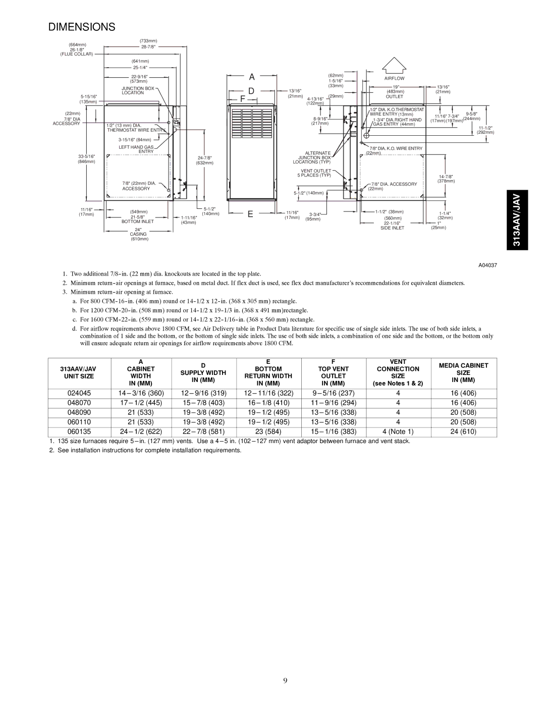
1.Two additional
2.Minimum
3.Minimum
a.For 800
b.For 1200
c.For 1600
d.For airflow requirements above 1800 CFM, see Air Delivery table in Product Data literature for specific use of single side inlets. The use of both side inlets, a combination of 1 side and the bottom, or the bottom of single side inlets. The use of both side inlets, a combination of one side and the bottom, or the bottom only will ensure adequate return air openings for airflow requirements above 1800 CFM.
|
| A |
| D |
| E |
| F | VENT | MEDIA CABINET | |
313AAV/JAV | CABINET |
| BOTTOM | TOP VENT | CONNECTION | ||||||
SUPPLY WIDTH | SIZE | ||||||||||
UNIT SIZE |
| WIDTH | RETURN WIDTH |
| OUTLET | SIZE | |||||
|
| IN (MM) |
| IN (MM) | |||||||
|
| IN (MM) |
|
| IN (MM) |
| IN (MM) | (see Notes 1 & 2) | |||
|
|
|
|
|
|
| |||||
|
|
|
|
|
|
|
|
|
|
| |
024045 |
|
|
|
|
|
|
|
|
|
| |
3/16 (360) | 9/16 (319) | 11/16 (322) | 5/16 (237) | 4 | 16 (406) | ||||||
048070 | 17 | 7/8 (403) | 16 | 9/16 (294) | 4 | 16 (406) | |||||
048090 |
| 21 (533) | 3/8 (492) | 19 | 5/16 (338) | 4 | 20 (508) | ||||
060110 |
| 21 (533) | 3/8 (492) | 19 | 5/16 (338) | 4 | 20 (508) | ||||
060135 | 24 | 7/8 (581) |
| 23 (584) | 1/16 (383) | 4 (Note 1) | 24 (610) | ||||
1.135 size furnaces require
2.See installation instructions for complete installation requirements.
9