CONNECTION DIAGRAM

LS

FRS2

LPS NOTE #8


RED


ORN


GRY


HPS

BRN

HI


YEL


P


RED


RED


LGPS


BRN


BLU


GV


DSS


C


M


ORN


GRN/YEL


GRN/YEL


RED


#8NOTE

USED)(WHEN

FSE


IDM


L1

BLK


FRS1


HSI


FUSED DISCONNECT

(WHEN USED)


ALS1


GRN/YEL


SWITCH (WHEN REQ’D)


ILK

JB


NOTE #1


SET-UP


(WHEN USED)


WHT


GRY


RED


HEAT


ORN

NOTE #6


PL6


WHT


L2

WHT


FU2


SWITCH


SWITCH


1

2


GND


1


2


NORM


ALS2

YEL


BLK


BLK

WHT


HI HT *


BLK


LO HT

ON OFF

ON OFF

ORN


WHT

1

2

3

PL3


BLOWER-


OFF DELAY SWITCH


WHT


RED


(SEC.)

3


4


BLK


90 SEC

*


PL2


BLK


135 SEC


1


WHT


7


180 SEC


2-STAGE


2

8


225 SEC


BLU

YEL


ON OFF

ONOFF CONTROL


3

9


FURNACE


FACTORY

SETTINGS


BLK


1


BLU

BRN

GRY

PR1

PR2


MED HI


YEL


GRN/YEL


HIGH-HEAT ONLY


GRN/YELP1


WHT


CAP


BLK


L1

L2


WHT


*


ORN


COMMON


NOTE #4

BRN

BRN


HI-COOL


4


BLOWER-OFF DELAY

RED


COM


WHT


TRAN


3


BLOWER-OFF DELAY

RED


HI-GAS EAC-2


HI


BLK


2


LOW-HEAT ONLY


HEAT


ON

OFF


321


12

LO-GAS

EAC-1


NOTE #15

MED

ORN


RED

BLU


TWIN


10

HEAT


MED LO


BLU


TEST

TJ


11

SPARE

SPARE


LO


BLWM


M


RED


8


SEC1


RED


LED S


BLU


W2

Com W/W1

Y/Y2 R

G HUM


SEC2

FU1


24V


LEGEND


TO 115VAC FIELD


SCHEMATIC DIAGRAM

(NATURAL GAS & PROPANE)

EQUIPMENT


DISCONNECT SWITCH


NOTE #1


GROUND


ILK


BHI / LOR


LO-GAS-HEAT


LO


L2


MED LO


BLWM


BHT / CLR


HI-GAS-HEAT


NOTE #15


L1

BLWR


SPARE

MED


HI

COM


HI-COOL

SPARE

MED HI


NOTE #4

BRN

BRN


COMMON


HSIR


EAC-1

EAC-2


CAP


PL2

3

PL6

1

HSI


2


IHI / LOR


9


LO


IDR


4

PL3

2

HI


1


7


3 COM

IDM


PR1


PR2


8


115VAC


FU1

SEC1

TRAN

SEC2


1


24VAC


HPSR

5 N/A


NOTE #5


6

N/A


2


12 N/A


FRS2


HUM


MGVR-2


2

FRS1


LS


3 (WHEN USED)


R


9


ALS2

ALS1


TWIN


TWINNING


TEST


6


S

JUMPER


PL1


DSS


TJ


W/W1


NOTE #8 LPS


M

5

(WHEN USED)


LGPS


SW1


NOTE #8


4


ALS1

AUXILIARY LIMIT SWITCH, OVERTEMP. MANUAL RESET, SPST (N.C.)

ALS2

AUXILIARY LIMIT SWITCH, OVERTEMP. AUTO RESET, SPST (N.C.)

BHI / LOR

BLOWER MOTOR SPEED CHANGE RELAY, SPDT

BHT / CLR BLOWER MOTOR SPEED CHANGE RELAY, SPDT

BLWM

BLOWER MOTOR, 4 or 5 -SPEED, PERMANENT-SPLIT-CAPACITOR

BLWR

BLOWER MOTOR RELAY, SPST (N.O.)

CAP

CAPACITOR

CPU

MICROPROCESSOR AND CIRCUITRY

DSS

DRAFT SAFEGUARD SWITCH (N.C.)

EAC-1

ELECTRONIC AIR CLEANER CONNECTION (115 VAC, 1 AMP MAX.)

EAC-2

ELECTRONIC AIR CLEANER CONNECTION (COMMON)

FRS1

FLAME ROLLOUT SWITCH OVERTEMP. MANUAL RESET, SPST (N.C.)

FRS2

FLAME ROLLOUT SWITCH OVERTEMP. MANUAL RESET, SPST (N.C.)

FSE

FLAME-PROVING SENSOR ELECTRODE

FU1

FUSE, 3 AMP, AUTOMOTIVE BLADE TYPE, FACTORY INSTALLED

FU2

FUSE, FIELD INSTALLED

GV

GAS VALVE, REDUNDANT LOW-HEAT OPERATORS, 2-STAGE

HPS

HIGH-HEAT PRESSURE SWITCH, SPST (N.O.)

MGVR

MAIN GAS VALVE RELAY, DPST (N.O.)


-1 = VALVE

-2 = HUMIDIFIER

PL1

12-CIRCUIT CONNECTOR

PL2

9-CIRCUIT CONNECTOR

PL3

3-CIRCUIT IDM CONNECTOR

PL6

2-CIRCUIT HSI CONNECTOR

SW1

HIGH-HEAT-ONLY SWITCH, SPST (MANUAL)*

SW2

LOW-HEAT-ONLY SWITCH, SPST (MANUAL)*

SW3 & 4

BLOWER-OFF DELAY SETTING SWITCHES,


SPST (MANUAL)*


TJ

TWINNING JUMPER, SPDT FOR MAIN OR


SECONDARY STATUS (MANUAL CHANGE OVER)

TRAN

TRANSFORMER-115VAC/24VAC

TWIN/TEST

1-CIRCUIT TWINNING BUSS CONNECTOR,


ALSO STATUS CODE RECALL

JUNCTION

TERMINAL

CONTROL TERMINAL


W2

CPU


HPS


MGVR-1


P

HI


1

M


Y/Y2

10

C

GV


NOTE#7


G


7


FSE


8 N/A


COM

11 N/A


NOTES:

SW4

SW3 SW2


HPSR

HIGH-HEAT PRESSURE SWITCH RELAY, SPST (N.C.)

HSI

HOT-SURFACE IGNITER (115 VAC)

HSIR

HOT-SURFACE IGNITOR RELAY, SPST (N.O.)

HUM

24VAC HUMIDIFIER CONNECTION (0.5 AMP. MAX.)

IDM

INDUCED DRAFT MOTOR, 2-SPEED, SHADED-POLE

IDR

INDUCER MOTOR RELAY, SPST (N.O.)

IHI / LOR

INDUCER MOTOR SPEED CHANGE RELAY, SPDT

ILK

BLOWER DOOR INTERLOCK SWITCH, SPST (N.O.)

JB

JUNCTION BOX

LED

LIGHT-EMITTING DIODE FOR STATUS CODES

LGPS

LOW GAS-PRESSURE SWITCH, SPST (N.O.)

LPS

LOW-HEAT PRESSURE SWITCH, SPST (N.O.)

LS

LIMIT SWITCH, OVERTEMPERATURE-AUTO RESET, SPST (N.C.)

FACTORY POWER WIRING (115VAC)

FACTORY CONTROL WIRING (24VAC) FIELD POWER WIRING (115VAC)

FIELD CONTROL WIRING (24VAC) CONDUCTOR ON CONTROL FIELD WIRING SCREW TERMINAL FIELD GROUND

EQUIPMENT GROUND

FIELD SPLICE

PLUG RECEPTACLE

1.Use only copper wire between the disconnect switch and the unit.

2.If any of the original wire, as supplied, must be replaced, use the same or equivalent type wire.

3.Inducer (IDM) and blower (BLWM) motors contain internal auto-reset thermal overload switches.

4.Blower motor speed selections are for average conditions. See Installation Instructions for details on optimum speed selection.

5.Replace only with a 3-AMP fuse.

6.Auxiliary limit switches (ALS1 & 2) used on some horizontal and some downflow models.

7.This wire must be connected to furnace sheet metal for control to prove flame.

8.Factory connected when LGPS not used.

9.Symbols are an electrical representation only.

10.BLOWER-ON DELAY: Gas heating 45 seconds, Cooling/Heat Pump 2 seconds.

11.Cooling/Heat Pump BLOWER-OFF DELAY is 90 seconds.

12.IGNITION-LOCKOUT will occur after four consecutive unsuccessful trials-for-ignition. Control will automatically reset after three hours.

13.Control must be grounded at pin 10 of 12-pin connector.

14.NA - Not Applicable

15.Spare terminal and wire not available on some applications. Insulate connector if not available.

324459-101 REV. D

A01365

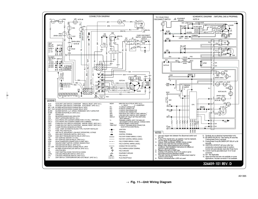
Fig. 11—Unit Wiring Diagram

Page 8
Image 8
Bryant 331JAV, 330JAV instruction manual 324459-101 REV. D

330JAV, 331JAV specifications

The Bryant 331JAV is a remarkable air conditioning unit that epitomizes efficiency, reliability, and advanced technology. Designed for residential use, the 331JAV series stands out with its Energy Star certification, ensuring that homeowners can enjoy optimal cooling while minimizing their energy consumption. This unit is particularly appealing to environmentally conscious individuals looking to reduce their carbon footprint without sacrificing comfort.

One of the key features of the Bryant 331JAV is its two-stage cooling system. This technology allows the unit to operate at varying speeds, adjusting its performance based on the home's cooling needs. By running at a lower speed for extended periods, the unit can maintain a consistent temperature with less energy consumption. This not only enhances comfort but also contributes to lower electricity bills.

In terms of design, the Bryant 331JAV boasts a compact and modern look, making it suitable for various home aesthetics. Its durable cabinet is designed to withstand harsh weather conditions, ensuring longevity and reliable performance. Additionally, the unit is equipped with a quiet operation system, which helps to maintain a peaceful indoor environment while cooling.

The Bryant 331JAV also incorporates advanced refrigerant technologies. It utilizes R-410A refrigerant, which is known for its efficiency and safety, as it does not harm the ozone layer. This focus on eco-friendly materials further underscores Bryant's commitment to sustainability.

Connectivity is another notable characteristic of the Bryant 331JAV. The unit is compatible with smart thermostats, allowing homeowners to control their cooling systems remotely through smartphones or other devices. This feature not only adds convenience but also enhances energy management, as users can adjust settings according to their schedules.

Furthermore, the unit has multiple capacity options, ensuring that it can be tailored to meet the specific needs of different homes. It is also designed for easy installation and maintenance, with accessible components that simplify service tasks.

Overall, the Bryant 331JAV is an exemplary choice for any homeowner looking to invest in a cutting-edge air conditioning system. With its combination of energy efficiency, advanced technology, and user-friendly features, it represents a significant leap forward in residential climate control solutions.