322869-101 REV. H

Ð7Ð


SW2


(WHEN USED)

(WHEN USED)


PCB


BLOWER


G


NOTE #14

NOTE #11


(WHEN USED)

NOTE #9


R

DSS


BVSS

ALS

PRS

LGPS


OFF


Y


(NOT ON ALL MODELS)

DELAY

SW1


W

ORN

ORN

ORN

ORN

ORN


BLOWER OFF DELAY


COM


SELECTION CHART


HUM


YEL


NOTE #13


90

SEC


TEST/TWIN


NOTE #14


135 SEC


LED


BLU

LS


NOTE #15


180 SEC


RED


225 SEC


PL1

3

2

1


(WHEN USED) NOTE #11


GV


WHT


6

5

4


FSE


FL


GVR


9

8

7


RED


FRS1

FRS2


GRN/YEL


SEC-1

SEC-2


GRN/YEL


NOTE #5


BLU


BLK


HI/LO


TRAN


RELAY


RED

WHT


24 VAC-3A


WHT (COM)


FU1

FUSE


BLK (HI)


GRN/YEL


BLOWER


HSIR

IDR

BLWR

COOL


BRN


SPEED

SPARE-1


OL


SELECT


YEL (MED HI)


START


L2

HEAT

SPARE-2

NOTE #7


CAP


PL3


EAC-1


120

VAC


PL2

2

PR2


AMP

BLU (MED LO)


BRN


1


1


L1

PR1


2

3

COM


EAC-2

1.5

RED

(LO)


BLWM


WHT


WHT (COM)

WHT


BLK

BLK

BLK

WHT


BLK


PL5


FUSED DISCONNECT


WHT


ILK

JB

SWITCH (WHEN REQ’D)


1

2


NOTE #4


IDM


L1


BLK


BLK


FU2


GRN/YEL


HSI


WHT


NEUTRAL


GND


TO 115VAC FIELD DISCONNECT


SCHEMATIC DIAGRAM

L1

L2


(NATURAL GAS & PROPANE)

NOTE #4


EQUIPMENT GROUND


ILK


LO


L2


SPARE-2


MED LO


HEAT


MED HI


SPARE-1


HI

START


HI/LO


OL

L1

BLWR


NOTE #7


COOL


CAP


COM


COM


BLWM


EAC-1


HSIR


EAC-2


1


1

HSI


PL2

2

PL5

2


IDM


IDR


PR1

115VAC


PR2

1


TRAN


3

PL3


24VAC


2

NOT USED


TEST/TWIN

FU1

NOTE #6


SEC-1


SEC-2


FRS1


FRS2

NOTE #12


GVR-2


7


HUM


(WHEN USED)


FL


1

NOTE #11


R


LS


NOTE #13


W


NOTE #13

LGPS

PRS


4

PL1

(WHEN USED)


HSIR

BLWR


HI/LO


(WHEN USED)


IDR


GVR


DSS

NOTE #14


BVSS


3


ALS


NOTE #14


(WHEN USED)


NOTE #15


CPU


GVR-1


2


GV


Y


LEGEND

ALS

AUXILIARY LIMIT SWITCH, OVERTEMP. -MANUAL RESET, SPST-(N.C.)

BLWR

BLOWER MOTOR RELAY, SPST-(N.O.)

BLWM

BLOWER MOTOR

BVSS

BLOCKED VENT SHUTOFF SWITCH, SPST - (N.C.)

CAP

CAPACITOR

CPU

MICROPROCESSOR AND CIRCUITRY

DSS

DRAFT SAFEGUARD SWITCH

EAC-1 ELECTRONIC AIR CLEANER CONNECTION (115 VAC 1.5 AMP MAX.)

EAC-2 ELECTRONIC AIR CLEANER CONNECTION (COMMON)

FL

FUSIBLE LINK

FRS

FLAME ROLLOUT SW. -MANUAL RESET, SPST-(N.C.)

FSE

FLAME PROVING ELECTRODE

FU1

FUSE, 3 AMP, AUTOMOTIVE BLADE TYPE, FACTORY INSTALLED

FU2

FUSE OR CIRCUIT BREAKER CURRENT INTERRUPT DEVICE


(FIELD INSTALLED & SUPPLIED)

GV

GAS VALVE-REDUNDANT OPERATORS

GVR

GAS VALVE RELAY, DPST-(N.O.)

HI/LO

BLOWER MOTOR SPEED CHANGE RELAY, SPDT

HSI

HOT SURFACE IGNITOR (115 VAC)

HSIR

HOT SURFACE IGNITOR RELAY, SPST-(N.O.)

HUM

24VAC HUMIDIFIER CONNECTION (.5 AMP. MAX.)

IDM

INDUCED DRAFT MOTOR

IDR

INDUCED DRAFT RELAY, SPST-(N.O.)

ILK

BLOWER ACCESS PANEL INTERLOCK SWITCH, SPST-(N.O.)

JB

JUNCTION BOX

LED

LIGHT-EMITTING DIODE FOR STATUS CODES

LGPS

LOW GAS PRESSURE SWITCH, SPST-(N.O.)

LS

LIMIT SWITCH, AUTO RESET, SPST(N.C.)

OL

AUTO-RESET INTERNAL MOTOR OVERLOAD TEMP. SW.


PCB

PRINTED CIRCUIT BOARD


PL1

9-CIRCUIT CONNECTOR


PL2

2-CIRCUIT PCB CONNECTOR


PL3

3-CIRCUIT IDM CONNECTOR


PL5

2-CIRCUIT HSI/PCB CONNECTOR


PRS

PRESSURE SWITCH, SPST-(N.O.)


TEST/TWIN

COMPONENT TEST & TWIN TERMINAL


TRAN

TRANSFORMER-115VAC/24VAC


JUNCTION


UNMARKED TERMINAL


PCB TERMINAL


FACTORY WIRING (115VAC)


FACTORY WIRING (24VAC)


FIELD WIRING (115VAC)


FIELD WIRING (24VAC)


CONDUCTOR ON PCB


FIELD WIRING TERMINAL


FIELD GROUND


EQUIPMENT GROUND


FIELD SPLICE


PLUG RECEPTACLE

8

NOTE #5


G


5

FSE


6

NOT USED

COM

NOT USED

9

NOTES:

1.If any of the original equipment wire is replaced use wire rated for 105°C.

2.Inducer (IDM) and blower (BLWM) motors contain internal auto-reset thermal overload switches (OL).

3.Blower motor speed selections are for average conditions, see installation instructions for details on optimum speed selection.

4.Use only copper wire between the disconnect switch and the furnace junction box (JB).

5.This wire must be connected to furnace sheetmetal for control to detect flame.

6.Replace only with a 3 amp fuse.

7.Yellow lead not on all motors.

8.Blower-on delay, gas heating 45 seconds, cooling or heat pump 2 seconds.

9.Blower-off delay, gas heating 90, 135, 180 or 225 seconds, cooling or heat pump 90 seconds.

(135 seconds only on some models)

10.Ignition-lockout will occur after four consecutive unsuccessful trials-for-ignition. Control will auto-reset after three hours.

11.When used, auxiliary limit switch (ALS) is on some downflow models only. When used, FL is on upflow models only.

12.Some models may have spade quick connect terminals.

13.Factory connected when LGPS is not used.

14.Factory connected when BVSS is not used. BVSS used when Chimney Adapter Accessory Kit is installed.

15. Gas valve leads are interchangeable on single stage valves.

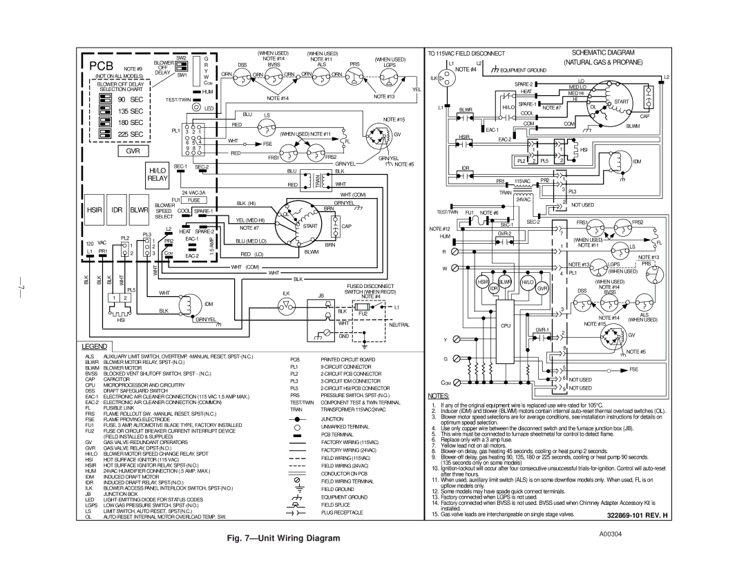
Fig. 7ÐUnit Wiring Diagram

A00304

Page 7
Image 7
Bryant 393AAV instruction manual Pcb, Ð7Ð

393AAV specifications

The Bryant 393AAV is a high-efficiency gas furnace designed to deliver reliable heating performance for residential applications. Crafted for homeowners seeking both comfort and energy savings, this model combines advanced technology with robust features to ensure optimal indoor climate control.

One of the standout characteristics of the Bryant 393AAV is its variable-speed ECM blower motor. This innovative motor allows for smooth and quiet operation while also enhancing energy efficiency. By adjusting its speed based on the heating demands of the home, the unit promotes consistent temperatures and improved airflow, ensuring that every room is evenly heated.

The furnace has an Annual Fuel Utilization Efficiency (AFUE) rating of up to 96.5%, making it one of the most efficient options available. This high AFUE rating signifies that a significant portion of the fuel consumed is converted into usable heat, leading to reduced utility bills and a smaller carbon footprint. The 393AAV’s two-stage gas valve further contributes to its efficiency. By operating at a lower capacity during milder conditions and switching to a higher capacity when temperatures drop, this feature allows homeowners to enjoy a comfortable environment while minimizing energy consumption.

In terms of durability, the Bryant 393AAV is built to last. It features a corrosion-resistant heat exchanger constructed from premium materials to withstand the test of time. Additionally, the furnace is equipped with a reliable ignition system, ensuring safe and efficient startup with each heating cycle. The design includes an insulated cabinet that not only reduces noise levels but also improves energy efficiency by minimizing heat loss.

Installation and maintenance of the Bryant 393AAV are user-friendly. The unit has a compact design that makes it easier to fit into various spaces within the home. Regular maintenance is facilitated through access panels that allow technicians to reach key components with ease, promoting longevity and sustained performance.

In conclusion, the Bryant 393AAV is a modern gas furnace that excels in efficiency, comfort, and reliability. With features like a variable-speed blower motor, high AFUE ratings, and a robust design, homeowners can trust this unit to provide consistent heating while helping to reduce overall energy costs. This furnace is an excellent choice for those looking to invest in a heating solution that aligns with both comfort and sustainability goals.