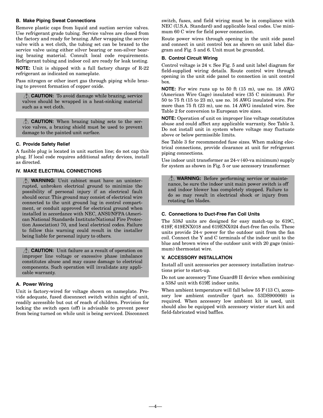
538J-18-1 specifications
The Bryant 538J-18-1 is a high-performance air conditioning unit designed to provide optimal comfort and efficiency in residential and light commercial settings. This model is notable for its advanced technology and robust design, catering to the needs of modern consumers looking for reliable climate control solutions.One of the main features of the Bryant 538J-18-1 is its energy-efficient operation. Equipped with a SEER (Seasonal Energy Efficiency Ratio) rating that exceeds the minimum standards, this unit helps homeowners save on energy costs while reducing their environmental footprint. The unit’s compressor utilizes variable speed technology, allowing it to adjust its operation based on cooling demand. This not only enhances energy efficiency but also contributes to quieter performance.
The Bryant 538J-18-1 is constructed with durable materials to endure various weather conditions. Its cabinet is made with galvanized steel, ensuring longevity and resistance to rust. Additionally, the unit features a powder-coated finish that protects against UV rays and other environmental stressors, enhancing both aesthetics and durability.
Smart technologies are integrated into the Bryant 538J-18-1, making it compatible with advanced climate control systems. The unit can be seamlessly connected to smart thermostats, allowing users to monitor and adjust settings remotely through mobile applications. This feature promotes convenience and allows for precise temperature control, ensuring optimal comfort throughout the home.
The unit's refrigerant choice also reflects a commitment to environmental responsibility. The Bryant 538J-18-1 utilizes R-410A refrigerant, which is known for its lower impact on the ozone layer compared to older refrigerants. Furthermore, the unit is designed for easier serviceability, with access panels that simplify maintenance and repairs.
In terms of specifications, the Bryant 538J-18-1 boasts a cooling capacity of 1.5 tons, making it suitable for a variety of indoor environments. The operational sound levels are minimal due to its innovative design, which incorporates sound-dampening features, ensuring a peaceful atmosphere.
Overall, the Bryant 538J-18-1 stands out as a reliable, efficient, and technologically advanced air conditioning solution, making it an excellent choice for those seeking comfort without compromising on sustainability or performance. With its array of features and innovative technologies, this unit is well-equipped to meet the diverse needs of modern living spaces.

