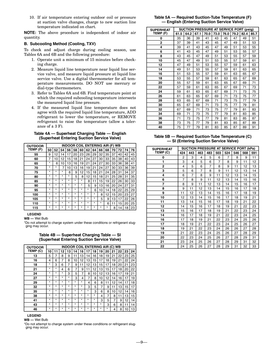
10.If air temperature entering outdoor coil or pressure at suction valve changes, charge to new suction line temperature indicated on chart.

NOTE: The above procedure is independent of indoor air quantity.

B. Subcooling Method (Cooling, TXV)

To check and adjust charge during cooling season, use Tables 6A and 6B and the following procedure:

1.Operate unit a minimum of 15 minutes before check- ing charge.

2.Measure liquid line temperature near liquid line ser- vice valve, and measure liquid pressure at liquid line service valve. Use a digital thermometer for all tem- perature measurements. DO NOT use mercury or dial-type thermometers.

3.Refer to Tables 6A and 6B. Find temperature point at which the required subcooling temperature intersects the measured liquid line pressure.

4.If the measured liquid line temperature does not agree with the required liquid line temperature, ADD refrigerant to lower the temperature, or REMOVE refrigerant to raise the temperature (allow a toler- ance of ± 3 F).

Table 4A — Superheat Charging Table — English

(Superheat Entering Suction Service Valve)

OUTDOOR


INDOOR COIL ENTERING AIR (F) WB


TEMP (F)

50

52

54

56

58

60

62

64

66

68

70

72

74

76

55

9

12

14

17

20

23

26

29

32

35

37

40

42

45

60

7

10

12

15

18

21

24

27

30

33

35

38

40

43

65

*

6

10

13

16

19

21

24

27

30

33

36

38

41

70

*

*

7

10

13

16

19

21

24

27

30

33

36

39

75

*

*

*

6

9

12

15

18

21

24

28

31

34

37

80

*

*

*

*

5

8

12

15

18

21

25

28

31

35

85

*

*

*

*

*

*

8

11

15

19

22

26

30

33

90

*

*

*

*

*

*

5

9

13

16

20

24

27

31

95

*

*

*

*

*

*

*

6

10

14

18

22

25

29

100

*

*

*

*

*

*

*

*

8

12

15

20

23

27

105

*

*

*

*

*

*

*

*

5

9

13

17

22

26

110

*

*

*

*

*

*

*

*

*

6

11

15

20

25

115

*

*

*

*

*

*

*

*

*

*

8

14

18

23

LEGEND

WB — Wet Bulb

*Do not attempt to charge system under these conditions or refrigerant slug- ging may occur.

Table 4B — Superheat Charging Table — SI (Superheat Entering Suction Service Valve)

OUTDOOR


INDOOR COIL ENTERING AIR (C) WB


TEMP (C)

10

11

12

13

14

16

17

18

19

20

21

22

23

24

13

5

7

8

9

11

13

14

16

18

19

21

22

23

25

16

4

6

7

8

10

12

13

15

17

18

19

21

22

24

18

*

3

6

7

9

11

12

13

15

17

18

20

21

23

21

*

*

4

6

7

9

11

12

13

15

17

18

20

22

24

*

*

*

3

5

7

8

10

12

13

16

17

19

21

27

*

*

*

*

3

4

7

8

10

12

14

16

17

19

29

*

*

*

*

*

*

4

6

8

11

12

14

17

18

32

*

*

*

*

*

*

3

5

7

9

11

13

15

17

35

*

*

*

*

*

*

*

3

6

8

10

12

14

16

38

*

*

*

*

*

*

*

*

4

7

8

11

13

15

41

*

*

*

*

*

*

*

*

3

5

7

9

12

14

43

*

*

*

*

*

*

*

*

*

3

6

8

11

14

46

*

*

*

*

*

*

*

*

*

*

4

8

10

13

LEGEND

WB — Wet Bulb

*Do not attempt to charge system under these conditions or refrigerant slug- ging may occur.

Table 5A — Required Suction-Tube Temperature (F)

— English (Entering Suction Service Valve)

SUPERHEAT

SUCTION PRESSURE AT SERVICE PORT (psig)

TEMP (F)

61.5

64.2

67.1

70.0

73.0

76.0

79.2

82.4

85.7

0

35

36

39

41

43

45

47

49

51

2

37

39

41

43

45

47

49

51

53

4

39

41

43

45

47

49

51

53

55

6

41

43

45

47

49

51

53

55

57

8

43

45

47

49

51

53

55

57

59

10

45

47

49

51

53

55

57

59

61

12

47

49

51

53

55

57

59

61

63

14

49

51

53

55

57

59

61

63

65

16

51

53

55

57

59

61

63

65

67

18

53

55

57

59

61

63

65

67

69

20

55

57

59

61

63

65

67

69

71

22

57

59

61

63

65

67

69

71

73

24

59

61

63

65

67

69

71

73

75

26

61

63

65

67

69

71

73

75

77

28

63

65

67

69

71

73

75

77

79

30

65

67

69

71

73

75

77

79

81

32

67

69

71

73

75

77

79

81

83

34

69

71

73

75

77

79

81

83

85

36

71

73

75

77

79

81

83

85

87

38

73

75

77

79

81

83

85

87

89

40

75

77

79

81

83

85

87

89

91

Table 5B — Required Suction-Tube Temperature (C)

— SI (Entering Suction Service Valve)

SUPERHEAT

SUCTION PRESSURE AT SERVICE PORT (kPa)

TEMP (C)

424

443

463

483

503

524

546

568

591

0

2

3

4

5

6

7

8

9

11

1

3

4

5

6

7

8

9

11

12

2

4

5

6

7

8

9

11

12

13

3

5

6

7

8

9

11

12

13

14

4

6

7

8

9

11

12

13

14

15

6

7

8

9

11

12

13

14

15

16

7

8

9

11

12

13

14

15

16

17

8

9

11

12

13

14

15

16

17

18

9

11

12

13

14

15

16

17

18

19

10

12

13

14

15

16

17

18

19

21

11

13

14

15

16

17

18

19

21

22

12

14

15

16

17

18

19

21

22

23

13

15

16

17

18

19

21

22

23

24

14

16

17

18

19

21

22

23

24

25

16

17

18

19

21

22

23

24

25

26

17

18

19

21

22

23

24

25

26

27

18

19

21

22

23

24

26

26

27

28

19

21

22

23

24

25

26

27

28

29

20

22

23

24

25

26

27

28

29

31

21

23

24

25

26

27

28

29

31

32

22

24

25

26

27

28

29

31

32

33

9

Page 9
Image 9
Bryant 538J-18-1 manual Subcooling Method Cooling, TXV, Outdoor Indoor Coil Entering AIR F WB Temp F

538J-18-1 specifications

The Bryant 538J-18-1 is a high-performance air conditioning unit designed to provide optimal comfort and efficiency in residential and light commercial settings. This model is notable for its advanced technology and robust design, catering to the needs of modern consumers looking for reliable climate control solutions.

One of the main features of the Bryant 538J-18-1 is its energy-efficient operation. Equipped with a SEER (Seasonal Energy Efficiency Ratio) rating that exceeds the minimum standards, this unit helps homeowners save on energy costs while reducing their environmental footprint. The unit’s compressor utilizes variable speed technology, allowing it to adjust its operation based on cooling demand. This not only enhances energy efficiency but also contributes to quieter performance.

The Bryant 538J-18-1 is constructed with durable materials to endure various weather conditions. Its cabinet is made with galvanized steel, ensuring longevity and resistance to rust. Additionally, the unit features a powder-coated finish that protects against UV rays and other environmental stressors, enhancing both aesthetics and durability.

Smart technologies are integrated into the Bryant 538J-18-1, making it compatible with advanced climate control systems. The unit can be seamlessly connected to smart thermostats, allowing users to monitor and adjust settings remotely through mobile applications. This feature promotes convenience and allows for precise temperature control, ensuring optimal comfort throughout the home.

The unit's refrigerant choice also reflects a commitment to environmental responsibility. The Bryant 538J-18-1 utilizes R-410A refrigerant, which is known for its lower impact on the ozone layer compared to older refrigerants. Furthermore, the unit is designed for easier serviceability, with access panels that simplify maintenance and repairs.

In terms of specifications, the Bryant 538J-18-1 boasts a cooling capacity of 1.5 tons, making it suitable for a variety of indoor environments. The operational sound levels are minimal due to its innovative design, which incorporates sound-dampening features, ensuring a peaceful atmosphere.

Overall, the Bryant 538J-18-1 stands out as a reliable, efficient, and technologically advanced air conditioning solution, making it an excellent choice for those seeking comfort without compromising on sustainability or performance. With its array of features and innovative technologies, this unit is well-equipped to meet the diverse needs of modern living spaces.