LIQUID-LINE

FILTER-DRIER

LIQUID


SERVICE


VALVE

R-41

0A

CONNECTOR

TUBE

A95509

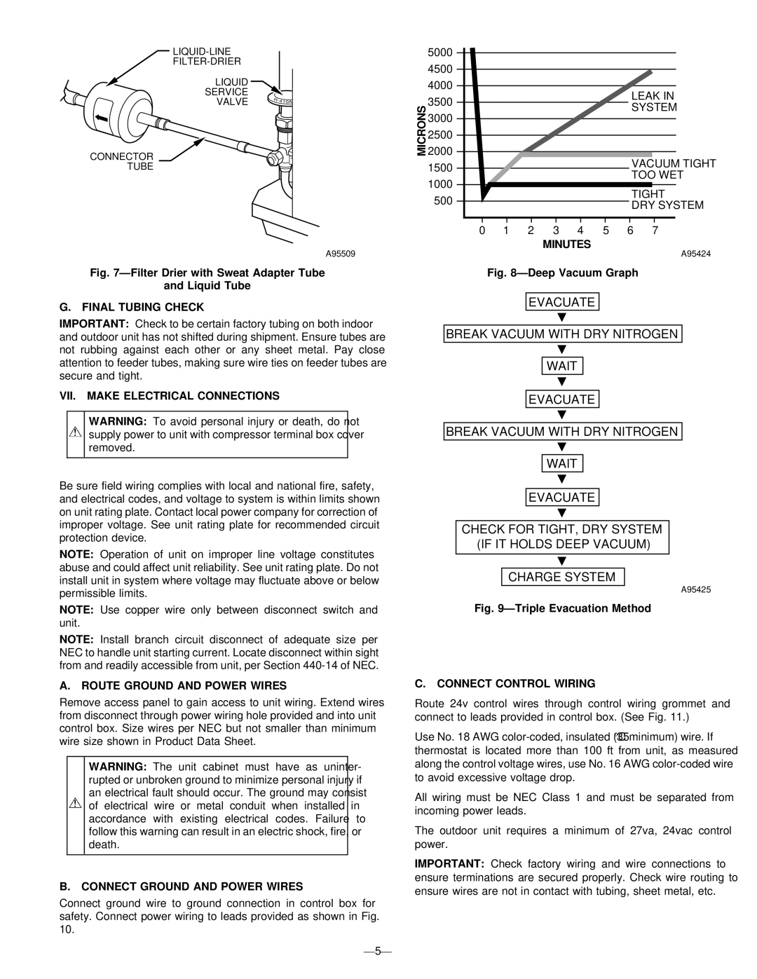
Fig. 7—Filter Drier with Sweat Adapter Tube

and Liquid Tube

G. FINAL TUBING CHECK

IMPORTANT: Check to be certain factory tubing on both indoor and outdoor unit has not shifted during shipment. Ensure tubes are not rubbing against each other or any sheet metal. Pay close attention to feeder tubes, making sure wire ties on feeder tubes are secure and tight.

VII. MAKE ELECTRICAL CONNECTIONS

WARNING: To avoid personal injury or death, do not supply power to unit with compressor terminal box cover removed.

Be sure field wiring complies with local and national fire, safety, and electrical codes, and voltage to system is within limits shown on unit rating plate. Contact local power company for correction of improper voltage. See unit rating plate for recommended circuit protection device.

NOTE: Operation of unit on improper line voltage constitutes abuse and could affect unit reliability. See unit rating plate. Do not install unit in system where voltage may fluctuate above or below permissible limits.

NOTE: Use copper wire only between disconnect switch and unit.

NOTE: Install branch circuit disconnect of adequate size per NEC to handle unit starting current. Locate disconnect within sight from and readily accessible from unit, per Section 440-14 of NEC.

A. ROUTE GROUND AND POWER WIRES

Remove access panel to gain access to unit wiring. Extend wires from disconnect through power wiring hole provided and into unit control box. Size wires per NEC but not smaller than minimum wire size shown in Product Data Sheet.

WARNING: The unit cabinet must have as uninter- rupted or unbroken ground to minimize personal injury if an electrical fault should occur. The ground may consist of electrical wire or metal conduit when installed in accordance with existing electrical codes. Failure to follow this warning can result in an electric shock, fire, or death.

B. CONNECT GROUND AND POWER WIRES

Connect ground wire to ground connection in control box for safety. Connect power wiring to leads provided as shown in Fig. 10.

—5—

5000


4500


4000


LEAK IN

3500


SYSTEM

3000


2500


MICRONS2000


VACUUM TIGHT

1500


TOO WET

1000


TIGHT

500


DRY SYSTEM


0

1

2

3

4

5

6

7


MINUTES


A95424


Fig. 8—Deep Vacuum Graph

EVACUATE

BREAK VACUUM WITH DRY NITROGEN

WAIT

EVACUATE

BREAK VACUUM WITH DRY NITROGEN

WAIT

EVACUATE

CHECK FOR TIGHT, DRY SYSTEM (IF IT HOLDS DEEP VACUUM)

CHARGE SYSTEM

A95425

Fig. 9—Triple Evacuation Method

C. CONNECT CONTROL WIRING

Route 24v control wires through control wiring grommet and connect to leads provided in control box. (See Fig. 11.)

Use No. 18 AWG color-coded, insulated (35°C minimum) wire. If thermostat is located more than 100 ft from unit, as measured along the control voltage wires, use No. 16 AWG color-coded wire to avoid excessive voltage drop.

All wiring must be NEC Class 1 and must be separated from incoming power leads.

The outdoor unit requires a minimum of 27va, 24vac control power.

IMPORTANT: Check factory wiring and wire connections to ensure terminations are secured properly. Check wire routing to ensure wires are not in contact with tubing, sheet metal, etc.

Page 5
Image 5
Bryant 598B instruction manual Final Tubing Check, VII. Make Electrical Connections, Route Ground and Power Wires, Minutes

598B specifications

The Bryant 598B, a model in the world of heating, ventilation, and air conditioning (HVAC) systems, stands out due to its efficient and reliable performance. This compact air conditioning unit is engineered to provide optimal cooling, making it an excellent choice for various residential and light commercial applications.

One of the main features of the Bryant 598B is its impressive SEER (Seasonal Energy Efficiency Ratio) rating, which indicates its energy efficiency in cooling mode. With a SEER rating that often exceeds industry standards, the 598B helps homeowners save on energy bills while minimizing their carbon footprint. This high efficiency is a key advantage, especially in regions experiencing extreme temperatures.

The Bryant 598B utilizes advanced technologies that enhance its overall performance and longevity. One of the standout technologies is the two-stage compressor, which allows the unit to operate at different cooling capacities depending on the current heat load. This capability not only improves comfort levels by maintaining consistent temperatures but also reduces wear and tear on the system, leading to extended lifespan and reliability.

Another noteworthy characteristic of the 598B is its quiet operation. Equipped with a sound-dampening design, the unit minimizes operational noise, ensuring peaceful indoor and outdoor environments. This feature is especially appreciated in areas where noise reduction is a priority, such as residential neighborhoods.

The Bryant 598B also comes with a durable cabinet built from high-quality materials that resist corrosion and withstand harsh weather conditions. This durability is crucial for maintaining performance over time, providing peace of mind for homeowners who invest in this HVAC solution.

Installation and maintenance of the Bryant 598B are facilitated by its user-friendly design. The unit includes features that allow for straightforward access to components, making service and upkeep more manageable for HVAC professionals.

In conclusion, the Bryant 598B air conditioning unit offers an appealing combination of energy efficiency, advanced technology, quiet operation, and durability. Whether for a new home or a system replacement, the Bryant 598B is an excellent choice for those seeking reliable and effective cooling solutions that align with modern efficiency standards.