113A / 114A / 116B
INSTALLATION
Check Equipment and Job Site
UNPACK UNIT
Move to final location. Remove carton taking care not to damage unit.
Inspect Equipment
File claim with shipping company prior to installation if shipment is damaged or incomplete. Locate unit rating plate on unit corner panel. It contains information needed to properly install unit. Check rating plate to be sure unit matches job specifications.
Install on a Solid, Level Mounting Pad
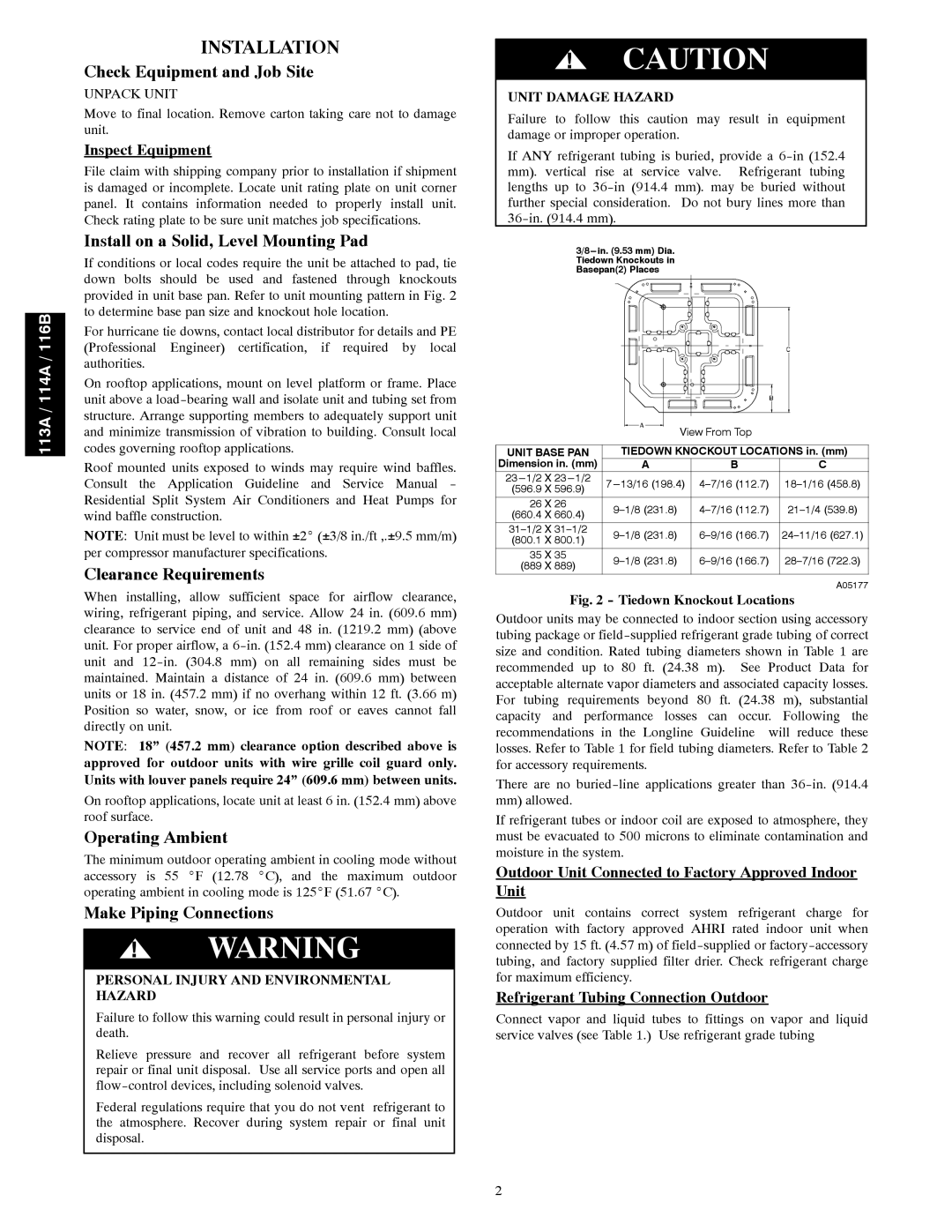
If conditions or local codes require the unit be attached to pad, tie down bolts should be used and fastened through knockouts provided in unit base pan. Refer to unit mounting pattern in Fig. 2 to determine base pan size and knockout hole location.
For hurricane tie downs, contact local distributor for details and PE (Professional Engineer) certification, if required by local authorities.
On rooftop applications, mount on level platform or frame. Place unit above a
Roof mounted units exposed to winds may require wind baffles. Consult the Application Guideline and Service Manual - Residential Split System Air Conditioners and Heat Pumps for wind baffle construction.
NOTE: Unit must be level to within ±2_ (±3/8 in./ft ,.±9.5 mm/m) per compressor manufacturer specifications.
Clearance Requirements
When installing, allow sufficient space for airflow clearance, wiring, refrigerant piping, and service. Allow 24 in. (609.6 mm) clearance to service end of unit and 48 in. (1219.2 mm) (above unit. For proper airflow, a
NOTE: 18” (457.2 mm) clearance option described above is approved for outdoor units with wire grille coil guard only. Units with louver panels require 24” (609.6 mm) between units.
On rooftop applications, locate unit at least 6 in. (152.4 mm) above roof surface.
Operating Ambient
The minimum outdoor operating ambient in cooling mode without accessory is 55 _F (12.78 _C), and the maximum outdoor operating ambient in cooling mode is 125_F (51.67 _C).
Make Piping Connections
!WARNING
PERSONAL INJURY AND ENVIRONMENTAL HAZARD
Failure to follow this warning could result in personal injury or death.
Relieve pressure and recover all refrigerant before system repair or final unit disposal. Use all service ports and open all
Federal regulations require that you do not vent refrigerant to the atmosphere. Recover during system repair or final unit disposal.
!CAUTION
UNIT DAMAGE HAZARD
Failure to follow this caution may result in equipment damage or improper operation.
If ANY refrigerant tubing is buried, provide a
View From Top |
UNIT BASE PAN | TIEDOWN KNOCKOUT LOCATIONS in. (mm) | |||
Dimension in. (mm) | A | B | C | |
(596.9 X 596.9) | ||||
|
|
| ||
26 X 26 | ||||
(660.4 X 660.4) | ||||
|
|
| ||
(800.1 X 800.1) | ||||
|
|
| ||
35 X 35 | ||||
(889 X 889) | ||||
|
|
| ||
|
|
| A05177 | |
Fig. 2 - Tiedown Knockout Locations
Outdoor units may be connected to indoor section using accessory tubing package or
There are no
If refrigerant tubes or indoor coil are exposed to atmosphere, they must be evacuated to 500 microns to eliminate contamination and moisture in the system.
Outdoor Unit Connected to Factory Approved Indoor Unit
Outdoor unit contains correct system refrigerant charge for operation with factory approved AHRI rated indoor unit when connected by 15 ft. (4.57 m) of
Refrigerant Tubing Connection Outdoor
Connect vapor and liquid tubes to fittings on vapor and liquid service valves (see Table 1.) Use refrigerant grade tubing
2