9BSST specifications
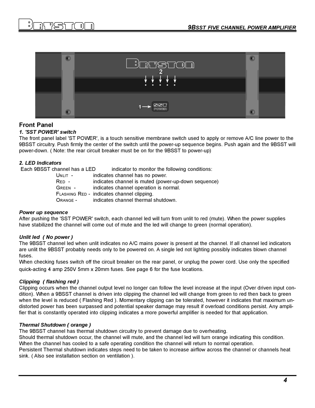
The Bryston 9BSST is a revered powerhouse in the realm of high-end audio amplification, offering audiophiles an unmatched listening experience through its impressive technical specifications and robust build quality. Esteemed for its pure, accurate sound reproduction, the 9BSST serves as a benchmark for solid-state amplifiers.One of the standout features of the Bryston 9BSST is its power output, delivering 300 watts per channel into 8 ohms and 500 watts into 4 ohms, making it versatile enough to drive a wide array of loudspeakers. This substantial power ensures that even the most demanding speakers are adequately supported, capable of producing deep, thunderous bass alongside pristine high frequencies.
The amplifier is constructed with Bryston's legendary attention to detail and durability. Its all-steel chassis not only provides a rigid structure but also helps in minimizing electromagnetic interference, contributing to the overall audio purity. The 9BSST is also known for its warm, transparent sound signature, which can be attributed to its well-engineered Class AB topology. This design strikes an excellent balance between delivering high power and maintaining low distortion levels.
Moreover, the 9BSST incorporates advanced thermal management systems, including large heat sinks and robust cooling fans, ensuring reliable performance during extended listening sessions. This prevents overheating, which can adversely affect performance and longevity. In terms of connectivity, the amplifier comes equipped with balanced XLR and unbalanced RCA inputs, providing flexibility in system integration.
Bryston amplifiers are also recognized for their longevity, a feature reinforced by their impressive 20-year warranty. This commitment to quality is indicative of the brand’s confidence in their products. In addition, the 9BSST includes Bryston's unique "low-frequency cutoff" feature, which protects speakers from potential damage caused by high power surges at lower frequencies.
Overall, the Bryston 9BSST encapsulates the perfect synergy of power, precision, and reliability. Its robust engineering and exceptional sound quality make it a favorite among audiophiles and music professionals alike, solidifying its status as a top-tier choice in the high-end amplifier market. With its rich history and dedication to performance, Bryston continues to set the standard for high fidelity audio.

