INTRODUCTION
Thank you for choosing this Bryston product. Bryston welcomes any suggestions or comments you may have about our products. We consider you, our customer, to be Bryston’s most important resource, and your opinion is very much appreciated.
MPS2 POWER SUPPLY SPECIFICATIONS:
Dimensions: 17” (or 19”) x 2.25” x 11”
Weight: actual: 15.5 lb. (7.03Kg) shipping: 19.3 lb. (8.75Kg)
Electrical:
Outputs: main outputs: | ±37V/250mA |
| +12V/350mA |
remote or switched trigger outputs: 12v @ ≤20mA ![]()
GENERAL DESCRIPTION
The MPS2 outboard power supply provides bipolar DC power for the various Bryston preamps and cross- overs, including the BP26 series of preamps, the BP1.5 Phono equalization stage and 10B crossovers specifi- cally designed to be used with external power supplies
The MPS2’s power ON/OFF switch is a toggle switch is located on the front panel along with a green LED to indicate power ON.
REMOTE ON/OFF FUNCTIONS
When the MPS2 is turned on, any BP26 preamps, or other Bryston products connected to its 4 main out- puts, will also be turned on. Also, any other equipment connected to the MPS2’s remote trigger outputs or switched remote trigger outputs may also be turned on.
On the rear of the unit there are five 2 pin terminal blocks that provide control signals for remote on/off functions.
REMOTE ACTIVATION of OTHER EQUIPMENT VIA THE MPS2
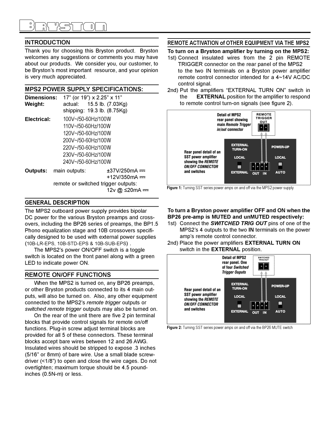
To turn on a Bryston amplifier by turning on the MPS2: 1st) Connect insulated wires from the 2 pin REMOTE TRIGGER connector on the rear panel of the MPS2
to the two IN terminals on a Bryston power amplifier remote control connector intended for a 4~14V AC/DC control signal.
2nd) Put the amplifiers “EXTERNAL TURN ON” switch in the EXTERNAL position for the amplifier to respond to remote control
Figure 1: Turning SST series power amps on and off via the MPS2 power supply
To turn a Bryston power amplifier OFF and ON when the BP26
MPS2’s 4 outputs to the two IN terminals on the power amp’s remote control connector.
2nd) Place the power amplifiers EXTERNAL TURN ON switch in the EXTERNAL position.