VII. OPTIONS, ACCESSORIES AND CONTROL SEQUENCES
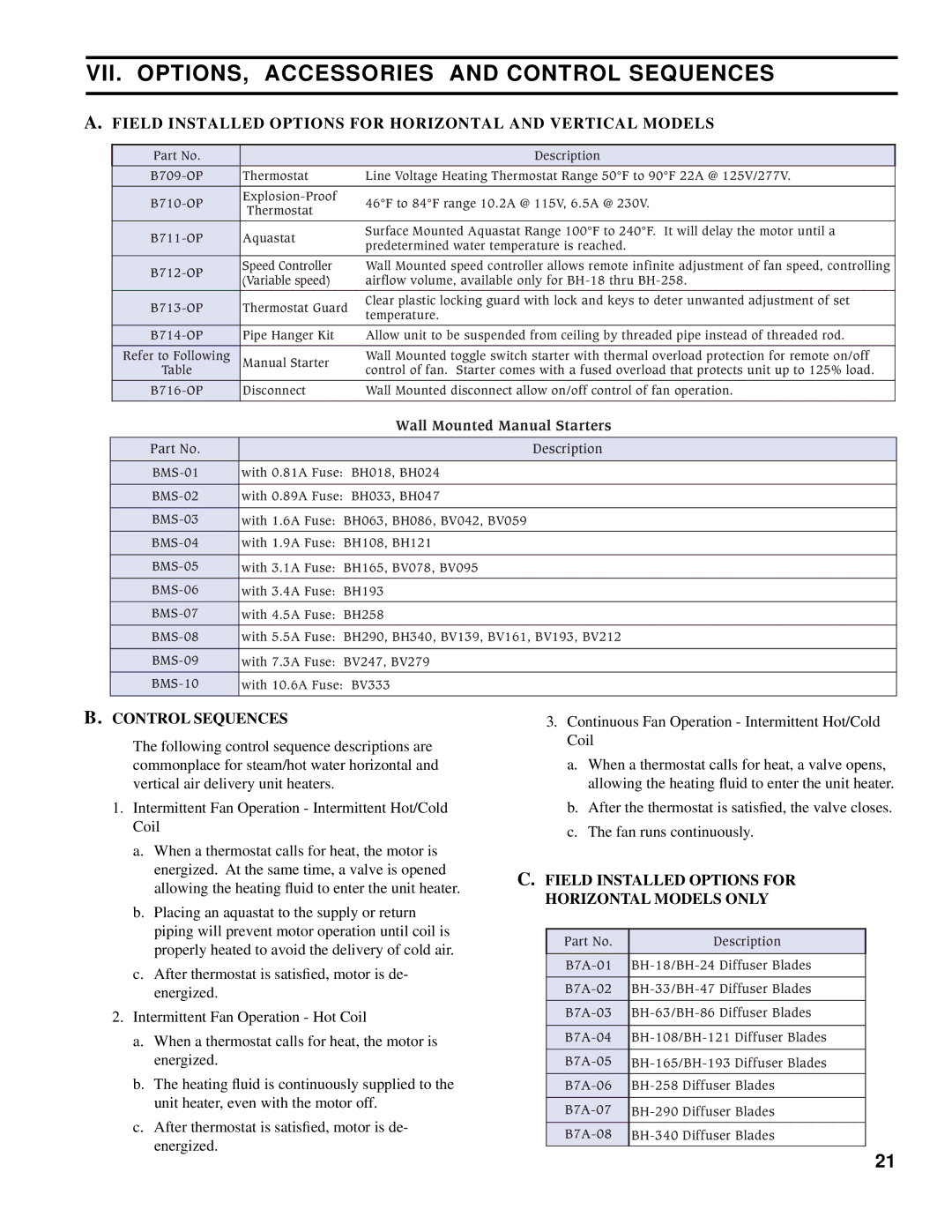
A.FIELD INSTALLED OPTIONS FOR HORIZONTAL AND VERTICAL MODELS
Part No. |
| Description | |
Thermostat | Line Voltage Heating Thermostat Range 50°F to 90°F 22A @ 125V/277V. | ||
46°F to 84°F range 10.2A @ 115V, 6.5A @ 230V. | |||
Thermostat | |||
|
| ||
Aquastat | Surface Mounted Aquastat Range 100°F to 240°F. It will delay the motor until a | ||
predetermined water temperature is reached. | |||
|
| ||
Speed Controller | Wall Mounted speed controller allows remote infinite adjustment of fan speed, controlling | ||
(Variable speed) | airflow volume, available only for | ||
| |||
Thermostat Guard | Clear plastic locking guard with lock and keys to deter unwanted adjustment of set | ||
temperature. | |||
|
| ||
Pipe Hanger Kit | Allow unit to be suspended from ceiling by threaded pipe instead of threaded rod. | ||
Refer to Following | Manual Starter | Wall Mounted toggle switch starter with thermal overload protection for remote on/off | |
Table |
| control of fan. Starter comes with a fused overload that protects unit up to 125% load. | |
Disconnect | Wall Mounted disconnect allow on/off control of fan operation. | ||
|
|
|
|
|
| Wall Mounted Manual Starters |
Part No. |
|
| Description |
with 0.81A | Fuse: BH018, BH024 | ||
with 0.89A | Fuse: BH033, BH047 | ||
with 1.6A Fuse: BH063, BH086, BV042, BV059 | |||
with 1.9A Fuse: BH108, BH121 | |||
with 3.1A Fuse: BH165, BV078, BV095 | |||
with 3.4A | Fuse: BH193 | ||
with 4.5A | Fuse: BH258 | ||
with 5.5A | Fuse: BH290, BH340, BV139, BV161, BV193, BV212 | ||
with 7.3A | Fuse: BV247, BV279 | ||
with 10.6A | Fuse: BV333 | ||
|
|
|
|
B.CONTROL SEQUENCES
The following control sequence descriptions are commonplace for steam/hot water horizontal and vertical air delivery unit heaters.
1.Intermittent Fan Operation - Intermittent Hot/Cold Coil
a.When a thermostat calls for heat, the motor is energized. At the same time, a valve is opened allowing the heating fluid to enter the unit heater.
b.Placing an aquastat to the supply or return piping will prevent motor operation until coil is properly heated to avoid the delivery of cold air.
c.After thermostat is satisfied, motor is de- energized.
2.Intermittent Fan Operation - Hot Coil
a.When a thermostat calls for heat, the motor is energized.
b.The heating fluid is continuously supplied to the unit heater, even with the motor off.
c.After thermostat is satisfied, motor is de- energized.
3.Continuous Fan Operation - Intermittent Hot/Cold Coil
a.When a thermostat calls for heat, a valve opens, allowing the heating fluid to enter the unit heater.
b.After the thermostat is satisfied, the valve closes.
c.The fan runs continuously.
C.FIELD INSTALLED OPTIONS FOR HORIZONTAL MODELS ONLY
Part No. | Description |
|
|
21