F.Install Electric Wiring in accordance with NATIONAL ELECTRICAL CODE and Local Regulations. The Burnham
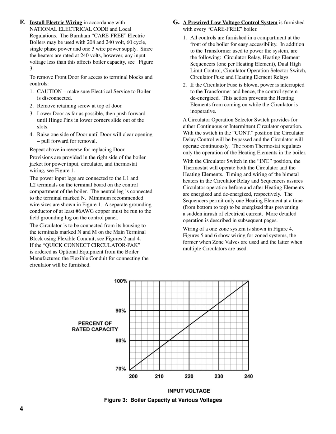
voltage less than this affects boiler capacity, see Figure 3.
To remove Front Door for access to terminal blocks and controls:
1.CAUTION – make sure Electrical Service to Boiler is disconnected.
2.Remove retaining screw at top of door.
3.Lower Door as far as possible, then push forward until Hinge Pins in lower corners slide out of the slots.
4.Raise one side of Door until Door will clear opening
– pull forward for removal.
Repeat above in reverse for replacing Door.
Provisions are provided in the right side of the boiler jacket for power input, circulator, and thermostat wiring, see Figure 1.
The power input legs are connected to the L1 and L2 terminals on the terminal board on the control compartment of the boiler. The neutral leg is connected to the terminal marked N. Minimum recommended wire sizes are shown in Figure 1. A separate grounding conductor of at least #6AWG copper must be run to the field grounding lug on the control panel.
The Circulator is to be connected from its housing to the terminals marked N and M on the Main Terminal Block using Flexible Conduit, see Figures 2 and 4.
If the “QUICK CONNECT
G.A Prewired Low Voltage Control System is furnished with every
1.All controls are furnished in a compartment at the front of the boiler for easy accessibility. In addition to the Transformer used to power the system, are the following: Circulator Relay, Heating Element Sequencers (one per Heating Element), Dual High Limit Control, Circulator Operation Selector Switch, Circulator Fuse and Heating Element Relays.
2.If the Circulator Fuse is blown, power is interrupted to the Transformer and hence, the control system
A Circulator Operation Selector Switch provides for either Continuous or Intermittent Circulator operation. With the switch in the “CONT.” position the Circulator Delay Control will be bypassed and the Circulator will operate continuously. The room Thermostat regulates only the operation of the Heating Elements in the boiler.
With the Circulator Switch in the “INT.” position, the Thermostat will operate both the Circulator and the Heating Elements. Timing and wiring of the bimetal heaters in the Circulator Relay and Sequencers assures Circulator operation before and after Heating Elements are energized and
Wiring of a one zone system is shown in Figure 4. Figures 5 and 6 show wiring for zoned systems, the former when Zone Valves are used and the latter when multiple Circulators are used.
Figure 3: Boiler Capacity at Various Voltages
4