5-2 3-POINT LIFT MODELS (287)
A.Attach
B.Place flex link and pivot tube between top of A- frame struts. Place support yokes on outside of A- frame struts. Fasten together using a 5/8” x 6” cap- screw and locknut. Attach the opposite ends of the support yokes over the welded strongback tubes which are located closest to the gearbox using 5/8” x 8” capscrews, flatwasher and locknut.
C.For single tailwheel mounting, position tail- wheel bracket on rear of cutter deck as shown. (Fig.
D.Place flatwasher on wheel spindle. Install wheel on tailwheel weldment securing with roll pin.
E.Bolt adjusting bracket to cutter deck using 5/8”
x2” capscrew and locknut.
F.Place tailwheel frame into desired position and fasten with 1/2” x
G.For mounting dual tailwheels, position tailwheel bracket at the rear tubes located in the strongbacks. (Fig.
H.Place flatwashers on wheel spindles. Install wheels on tailwheel weldment securing with roll pins.
I. Install lift pins and spacers according to Fig.
J. Attach clutch shield to gearbox as shown in exploded drawing in Figure
K.Remove pivot bolt from spline end of clutch. Remove inspection cover from clutch shield.
L.Slide clutch onto gearbox input shaft aligning bolt hole with slot in input shaft. Fasten with pivot bolt, lockwasher and nut. Torque to 30 ft./lbs.
M.Loosen eight nuts retaining clutch springs 1/3 turn or until spring can be turned with fingers.
N.With tractor at idle speed, engage tractor PTO drive
O.Retighten nuts to original position. If adjust- ment is necessary, refer to Section
![]() WARNING
WARNING ![]()
P.Fill gearbox with
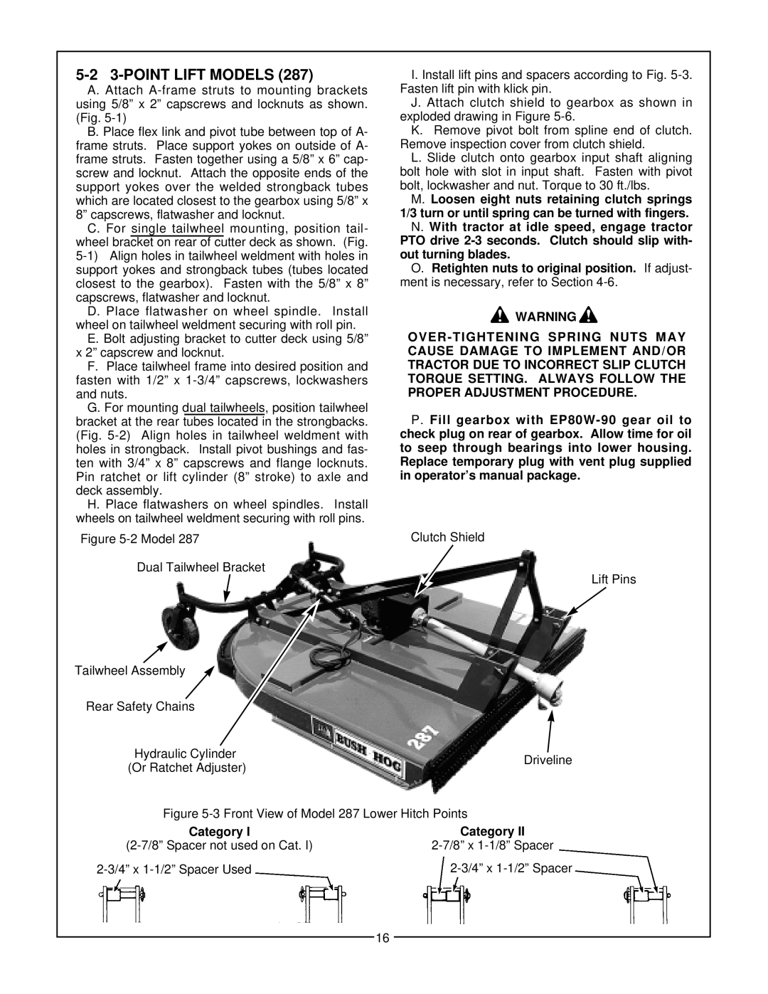
Figure |
| Clutch Shield |
Dual Tailwheel Bracket
Lift Pins
Tailwheel Assembly |
|
|
|
| ||||
|
|
|
|
| ||||
| Rear Safety Chains |
|
| |||||
|
|
|
|
|
|
|
| |
|
|
|
|
|
|
|
|
|
|
| Hydraulic Cylinder |
|
| ||||
| Driveline | |||||||
|
| (Or Ratchet Adjuster) |
|
| ||||
|
|
|
|
| ||||
|
|
|
|
|
|
|
|
|
|
|
|
|
|
|
|
|
|
|
|
| Figure |
|
| |||
|
|
|
|
|
|
|
|
|
Category I | Category II |
|
|
16