ASSEMBLY
ASSEMBLY
The basic Bush Hog 100 Series is shipped in two bundles - the Mainframe, the
Chock in a secure position while the Hydraulic Cylinders are inoperative or install the Tilt Pin to prevent tipping.
A Planer Wheel is provided as Accessory Equipment with this machine. It is shipped in two separate bundles. One bundle consists of the Mounting Bracket and the Planer Wheel Beam. The second bundle consists of the Caster Fork Arrangement. To assemble, drill two holes in the Mainframe as indicated by the drawing on the following page. Install the Mounting Bracket on the Mainframe of the Blade, then install the Caster Fork into the Planer Wheel Main Beam. Lubricate the two Bushings in the Planer Wheel Bracket at grease fittings provided.
Additional accessories are provided for use with the Planer Wheel: Hydraulic Cylinder or Ratchet Jack.
Your Bush Hog 100 Series is designed to be used with either a standard Category 1 or 2,
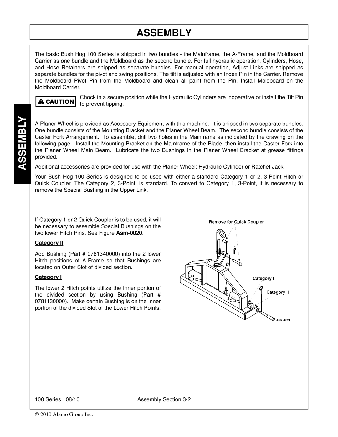
If Category 1 or 2 Quick Coupler is to be used, it will be necessary to assemble Special Bushings on the two lower Hitch Pins. See Figure
Category II
Add Bushing (Part # 0781340000) into the 2 lower Hitch positions of
Category I
The lower 2 Hitch points utilize the Inner portion of the divided section by using Bushing (Part # 0781130000). Make certain Bushing is on the Inner portion of the divided Slot of the Lower Hitch Points.
100 Series 08/10 | Assembly Section |
© 2010 Alamo Group Inc.