
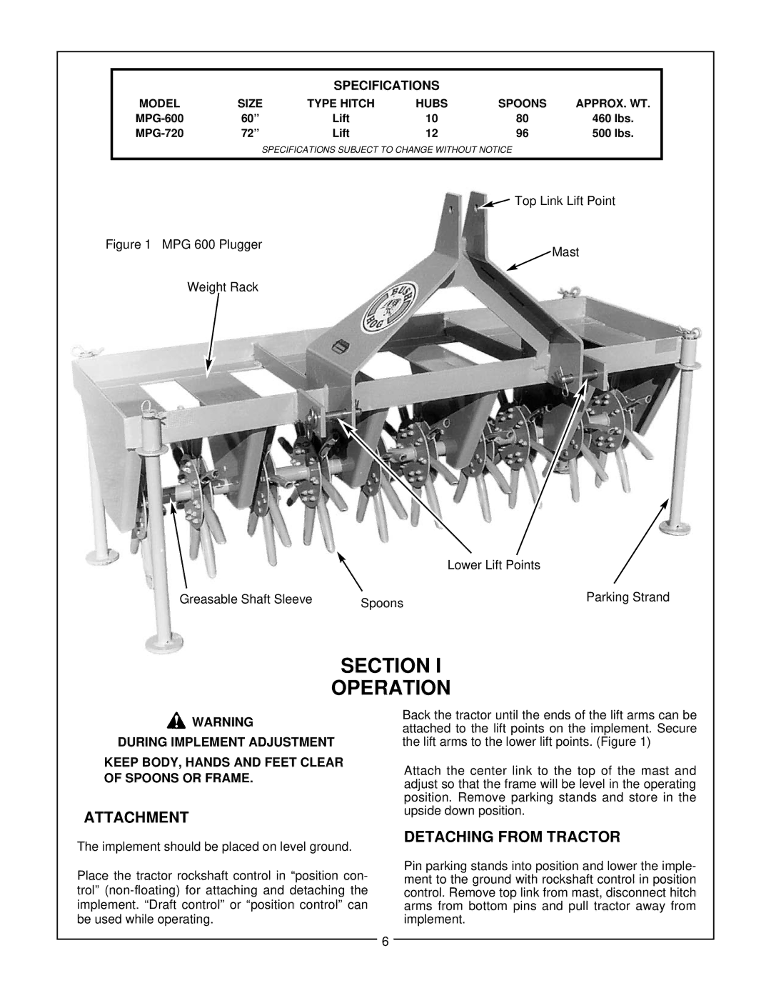
720, MPG 600 specifications
The Bush Hog MPG 600 and 720 are robust and versatile rotary mowers ideal for a variety of land management tasks. Designed for heavy-duty applications, these mowers are engineered to provide exceptional performance and durability, making them a popular choice among agricultural professionals, landscapers, and property owners.One of the primary features of the MPG 600 and 720 models is their impressive cutting width. The MPG 600 boasts a cutting width of 60 inches while the MPG 720 provides a wider 72-inch cutting path. This feature allows operators to cover large areas efficiently, reducing mowing time and increasing productivity. The mowers are equipped with high-quality blades that deliver a clean and precise cut, ensuring a professional finish every time.
Both models come with a sturdy, all-steel frame, which enhances their durability and resilience against harsh working conditions. This robust construction is complemented by a heavy-duty gear drive system that provides reliable power transmission from the tractor to the mower. Operators can expect smooth performance and reduced maintenance with this type of system, which is less prone to wear and tear compared to chain-driven alternatives.
Technologically, the MPG mowers are designed with versatility in mind. They can be easily attached to different types of tractors, making them suitable for various applications, including pasture management, wildlife habitat maintenance, and grass cutting in non-crop areas. The quick-attach feature allows for rapid setup and removal, enhancing usability.
The MPG models also incorporate advanced safety features, such as a removable guard and a heavy-duty shield that protects both the operator and bystanders from debris and potential hazards during operation. These safety features ensure that the mowers can be used confidently in a range of environments.
Another significant characteristic is the ability to adjust cutting height, allowing users to customize the mower settings based on the type of grass or terrain. This flexibility ensures optimal performance and helps maintain the health of the grass, promoting thicker and healthier growth.
In conclusion, the Bush Hog MPG 600 and 720 rotary mowers exemplify efficiency, durability, and versatility. Their robust construction, advanced technology, and user-friendly features make them a reliable choice for anyone in need of effective land management solutions. Whether for agricultural use or landscaping projects, these mowers stand ready to tackle the toughest mowing challenges with ease.